
Photovoltaic inverter system and method of starting same at high open-circuit voltage

一种逆变器、链路电压的技术,应用在太阳能发电领域,能够解决PV阵列与电力转换器系统断开、损坏电力转换器系统等问题

Active Publication Date: 2012-02-08
通用电气电网解决方案有限责任公司
View PDF4 Cites 4 Cited by
  • Summary
  • Abstract
  • Description
  • Claims
  • Application Information

AI Technical Summary

Problems solved by technology

However, during start-up or other transient conditions when the PV array is first coupled, decoupled, or recoupled to the converter, the power converter system may have to temporarily accommodate the PV array's open circuit voltage or other high source voltages
Transient conditions can cause the DC link voltage or PV array source voltage to exceed the overvoltage trip point of the power converter system, resulting in damage to the power converter system or disconnection of the PV array from the power converter system

Method used


Image

  • Photovoltaic inverter system and method of starting same at high open-circuit voltage
  • Photovoltaic inverter system and method of starting same at high open-circuit voltage
  • Photovoltaic inverter system and method of starting same at high open-circuit voltage

Examples


Embodiment Construction

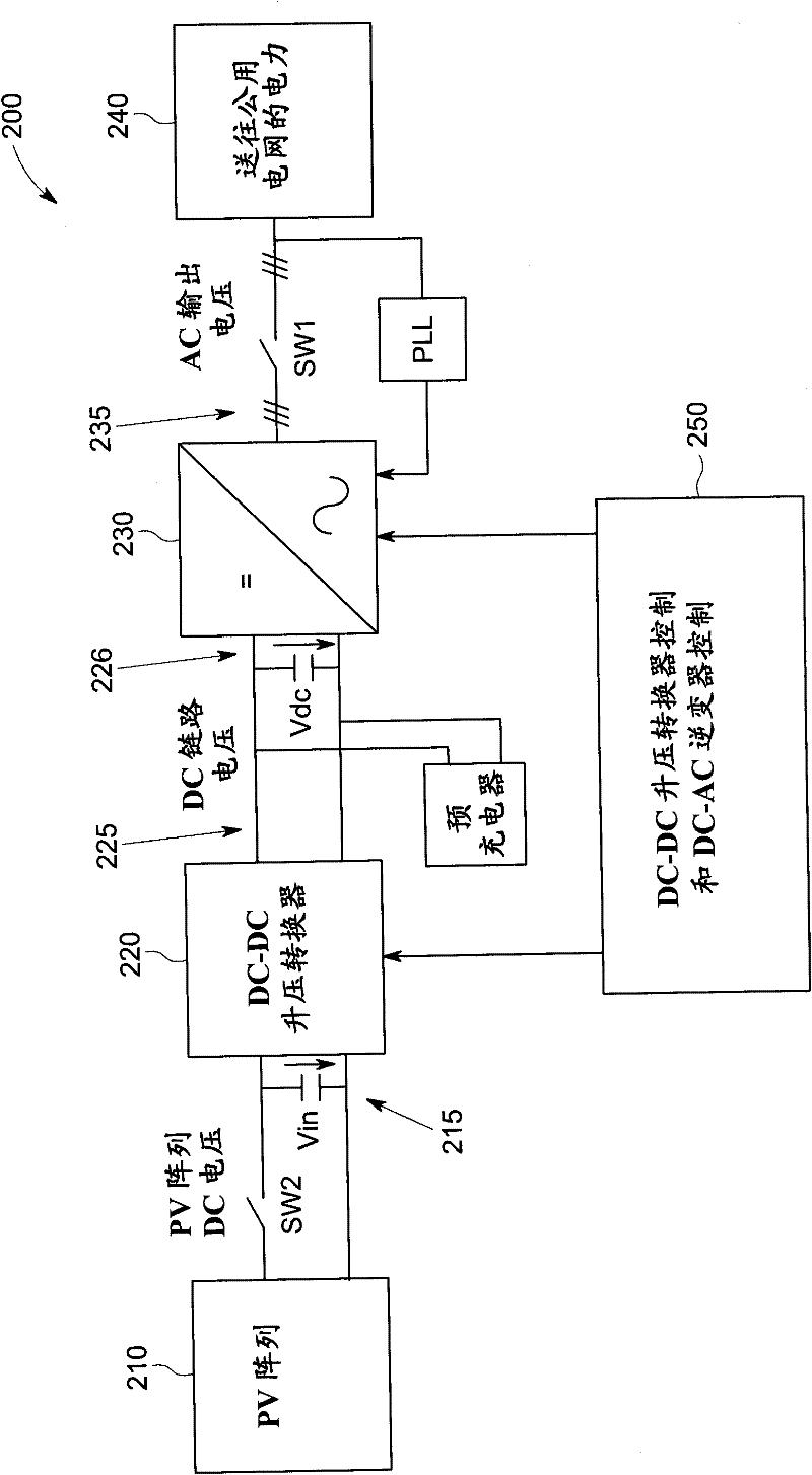
[0039] image 3 A block diagram of a two-stage PV power converter system 200 for converting DC power 215 generated by a PV array 210 to AC power 235 suitable for feeding an AC power grid 240 is shown. The first stage of the power converter system 200 can include a DC-DC converter 220 , such as a boost converter, which provides DC power 225 to a DC link 226 . DC link 226 couples DC-DC converter 220 to inverter 230 , which operates as the second stage of power converter 200 . Inverter 230 converts DC power 225 on DC link 226 to AC power 235 suitable for supplying to AC power grid 240 . The DC-DC converter 220 can be a part or integral part of the inverter 230 , or can be a stand-alone structure separate from the inverter 230 . Additionally, more than one converter 220 can be coupled to the same inverter 230 through one or more DC links.

[0040]Power converter system 200 includes control system 250 configured to control DC-DC boost converter 220 and DC-AC inverter 230 . For ...


PUM


Abstract

A power inverter system (200) includes a DC to AC inverter (230) configured to convert DC voltage from a DC power source (210) to AC voltage. A DC link (226) couples the DC power source (210) and the inverter (230). An inverter pre-charger (350) operates to pre-charge the inverter (230) to achieve a desired DC link voltage prior to connecting the power inverter system (200) to an AC power grid (240). A phased lock loop (352) synchronizes the pre-charged inverter (230) to the AC power grid (240) prior to connecting the power inverter system (200) to the AC power grid (240). The pre-charged inverter (230) regulates the DC link voltage to about the minimum voltage level that allows control of AC grid currents via the inverter (230) subsequent to connecting the power inverter system (200) to the AC grid (240). The inverter (230) operates in a maximum power point tracking control mode only subsequent to a first voltage transient caused by connecting the DC power source (210) to energize the power inverter system (200).

Description

technical field [0001] The present invention relates generally to the field of solar power generation, and more particularly to methods and systems that allow high DC source voltages in solar power converter systems. Background technique [0002] Solar power is becoming an increasing source of energy around the world. A solar power generation system typically includes one or more photovoltaic arrays (PV arrays) with a plurality of interconnected solar cells that convert solar energy to DC electricity through the photovoltaic effect. To interface the output of the PV array with the utility grid, a power converter system is used to convert the DC current and DC voltage output of the PV array into a 60 / 50Hz AC current waveform, which feeds power to the utility grid. [0003] Various power converter systems exist for interfacing the DC output of a PV array (or other DC power source) with an AC grid. One implementation of a power converter system includes two stages, a boost co...

Claims


Application Information

Patent Timeline
Patent Type & Authority Applications(China)
IPC IPC(8): H02M7/48H02M3/155H02M7/5387H02M1/36
CPCH02M3/1584H02M7/48H02J2300/22H02J2300/24H02J3/381Y02E10/56H02J2300/26H02J3/46
Inventor S·施勒德沈捷S·F·S·埃尔-巴巴里R·勒斯纳
Owner 通用电气电网解决方案有限责任公司
Features
  • Generate Ideas
  • Intellectual Property
  • Life Sciences
  • Materials
  • Tech Scout
  • Unparalleled Data Quality
  • Higher Quality Content
  • 60% Fewer Hallucinations
Learn More