

High fill subgrade connection method
A high fill and roadbed technology, applied in the directions of roads, roads, buildings, etc., can solve the problems of insignificant reduction in the amount of foundation treatment, it is difficult to ensure that the old pavement does not crack, and the driving safety is affected, so as to save the construction period, The effect of saving arable land resources and clear force
- Summary
- Abstract
- Description
- Claims
- Application Information
AI Technical Summary
Problems solved by technology
Method used
Image

Examples
Embodiment 1
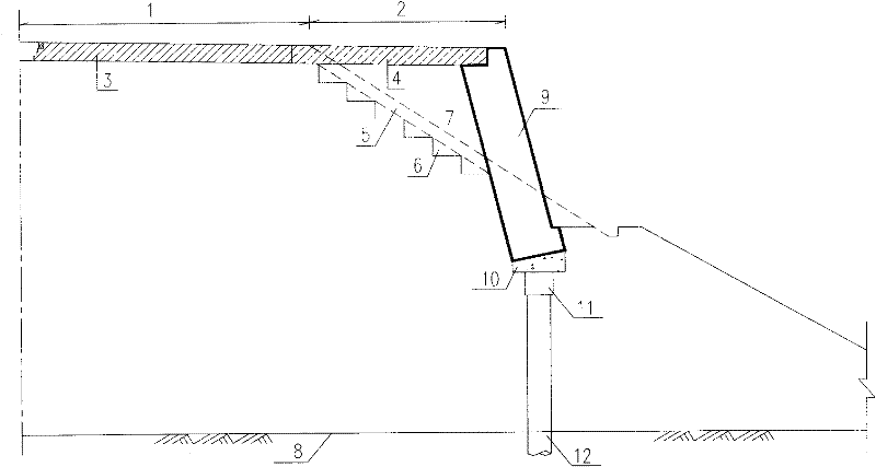
[0027] image 3 Shown is the method of splicing new and old subgrades by setting an inclined retaining wall on the upper slope to close the slope. It is in the vicinity of the 8m platform on the upper part of the high fill, to carry out the treatment of digging and filling concrete piles and the construction of the retaining structure. That is, the old roadbed 1 is excavated longitudinally on the side slope of the old roadbed 1 according to the inner slope ratio of the retaining structure, and the slope surface is temporarily supported 13 to ensure that the slope is stable, and then the hole-digging piles 12 are constructed according to the conventional method, and the piles are constructed. The pile diameter is generally 0.8 to 1.6 meters, and the pile length and longitudinal pile spacing need to be determined in conjunction with the bearing capacity requirements of the support and retaining structure, and are determined according to the conventional pile side friction resist...
Embodiment 2
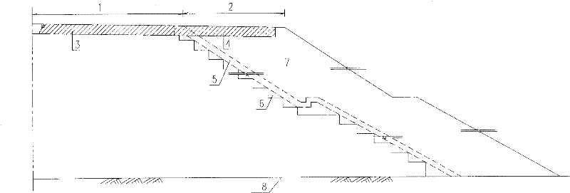
[0036] Figure 4 Shown is the method of splicing new and old subgrades by setting a counterweight retaining wall on the upper slope to close the slope. It is based on the scheme of Embodiment 1, because the volume of the counterweight retaining wall is slightly larger, and more excavation of the old roadbed 1 is required. Therefore, in order to ensure the stability of the old subgrade 1 when excavating, it is necessary to install anchors with a diameter of 20-28mm on the slope to be excavated before excavation. After excavating the old subgrade from top to bottom, immediately hang the anchor rod head exposed on the slope after excavation with a diameter ≥ 8mm, a mesh size of 20x20cm steel mesh and a support scheme of spraying 8-10cm C20 concrete to ensure During the construction of the retaining wall, the slope is stable, and after the foundation treatment is tested and passed, the crushed stone cushion 10 is set and the counterweight retaining wall 9 is constructed according...
Embodiment 3
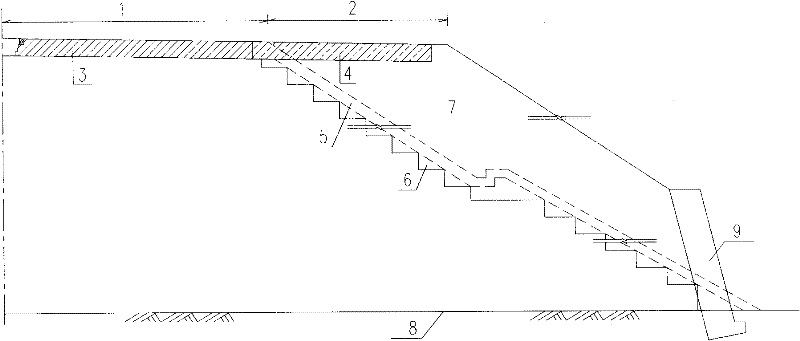
[0038] Figure 5Shown is the method of splicing old and new subgrades by setting buttress-type retaining walls on the upper slope to close the slope. It is on the basis of embodiment 1, example 2 scheme, carries out C25 reinforced concrete buttress retaining wall 9 construction. Due to the light weight of the retaining wall, the requirements for the bearing capacity of the foundation are relatively low, and the amount of foundation treatment under the wall bottom plate is less than that of Example 1 and Example 2. Steep slope excavation and support are the same as embodiment 2, and others are the same as embodiment 1.
PUM
| Property | Measurement | Unit |
|---|---|---|
| Thickness | aaaaa | aaaaa |
| Particle size | aaaaa | aaaaa |
Abstract
Description
Claims
Application Information