
Chip built-in resistance-capacitance (RC) oscillator

An oscillator and chip technology, applied in pulse generation, electrical components, and electrical pulse generation, etc., can solve the problems of MCU system working errors, occupying chips, increasing design costs, etc., to improve product competitiveness, ensure normal communication, reduce The effect of design cost

Active Publication Date: 2012-02-22
SINO WEALTH ELECTRONICS
View PDF3 Cites 8 Cited by
  • Summary
  • Abstract
  • Description
  • Claims
  • Application Information

AI Technical Summary

Problems solved by technology

[0008] It can be seen from the above expression that in the actual process, if the resistance material with a small first-order temperature coefficient TC cannot be found, the output frequency f of the on-chip RC oscillator will vary greatly with the operating temperature T , it exceeds ±2% in the working temperature range of -40°C ~ 85°C, which will easily lead to UART communication errors, resulting in MCU system work errors, and at the same time cannot meet the needs of precise timing modules
[0009] In addition, if the output frequency f of the built-in RC oscillator varies greatly with the operating temperature T, the MCU system needs an external crystal oscillator to provide the system clock in order to ensure the normal communication of the UART, which requires additional costs and occupies the chip. Two pins, increasing design cost

Method used


Image

  • Chip built-in resistance-capacitance (RC) oscillator
  • Chip built-in resistance-capacitance (RC) oscillator
  • Chip built-in resistance-capacitance (RC) oscillator

Examples


Embodiment Construction

[0041] The present invention will be further described below in conjunction with specific embodiment and accompanying drawing, set forth more details in the following description so as to fully understand the present invention, but the present invention can obviously be implemented in a variety of other ways different from this description, Those skilled in the art can make similar promotions and deductions based on actual application situations without violating the connotation of the present invention, so the content of this specific embodiment should not limit the protection scope of the present invention.

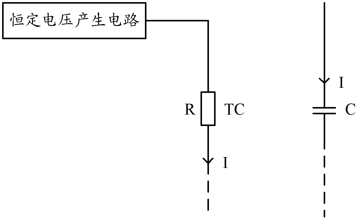
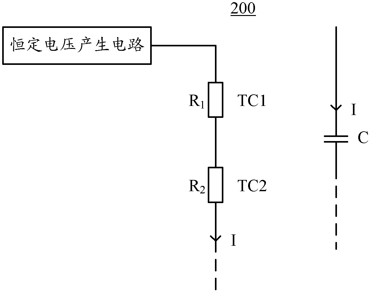
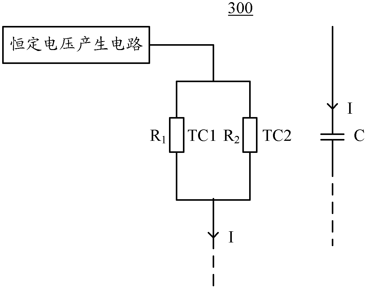
[0042] figure 2 It is a schematic diagram of the current generation principle of the on-chip RC oscillator according to an embodiment of the present invention. As shown in the figure, the on-chip RC oscillator may include a constant voltage generating circuit, a first resistor R 1 , the second resistance R 2 and capacitor C. In this example, the label R 1 , R 2 It...


PUM


Abstract

The invention provides a chip built-in resistance-capacitance (RC) oscillator, which comprises a constant voltage generating circuit, a plurality of resistors and a capacitor, wherein the constant voltage generating circuit is used for generating a constant voltage; the resistors are connected in parallel or in series or connected in a mixed mode to form a resistor network, and one end of the resistor network is connected with the constant voltage generating circuit; the capacitor is connected with the other end of the resistor network; and the temperature coefficient of an equivalent resistance value of the resistor network is configured as a required value. With the configuration of the resistance value of each resistor in the resistor network of the RC oscillator, and with the adoptionof mutual compensation of resistors with different temperature coefficients, the variation of the output frequency of the RC oscillator along temperature is greatly reduced to ensure that the RC oscillator is in a working temperature range of between -40 and 85 DEG C, and the resistance temperature coefficient compensation matching of different materials in the manufacturing process is good and the variation of the output frequency can be less than + / -0.5 percent so that the chip built-in resistance-capacitance (RC) oscillator can be applied in fields with high requirement on frequency such as timing, communication and the like.

Description

technical field [0001] The invention relates to the technical fields of analog integrated circuit design, MCU communication and timing, and in particular, the invention relates to a chip built-in RC oscillator. Background technique [0002] The components of the RC oscillator integrated in the current microprocessor (MCU) chip mainly include: BIAS current generation circuit (including resistors), capacitors, comparators, and frequency generation, which are provided to the MCU system clock for general asynchronous reception / transmission Device (Universal Asynchronous Receiver / Transmitter, referred to as UART) communication. [0003] The principle of current generation in an RC oscillator in the prior art can be as follows figure 1 shown. The constant voltage generating circuit is connected to a resistor R with a temperature coefficient TC, and then connected to a capacitor C to generate a current I in the circuit. Wherein, I*t=C*ΔV, t is the oscillation period, and ΔV is t...

Claims


Application Information

Patent Timeline
IPC IPC(8): H03K3/011
Inventor 蒙蕾
Owner SINO WEALTH ELECTRONICS
Features
  • Generate Ideas
  • Intellectual Property
  • Life Sciences
  • Materials
  • Tech Scout
  • Unparalleled Data Quality
  • Higher Quality Content
  • 60% Fewer Hallucinations
Learn More