
Device and method for cooling welded rail section

A technology of track welding and cooling method, which is applied in the direction of track, track maintenance, track laying, etc., can solve the problem that the residual stress of the track welding part cannot be reduced, and achieve the effects of improving fatigue strength, precise temperature control, and reducing residual stress

Inactive Publication Date: 2012-02-22
NIPPON STEEL CORP
View PDF12 Cites 8 Cited by
  • Summary
  • Abstract
  • Description
  • Claims
  • Application Information

AI Technical Summary

Problems solved by technology

That is, it is known that the residual stress of the orbital weld cannot be reduced unless the appropriate range of the orbital weld is cooled at an appropriate cooling rate.

Method used


Image

  • Device and method for cooling welded rail section
  • Device and method for cooling welded rail section
  • Device and method for cooling welded rail section

Examples


Embodiment

[0093] [Cooling test of orbital welded part]

[0094] Next, a cooling test of an orbital welded portion performed using the cooling device 10 will be described. Table 1 shows the examples of the present invention, and Table 2 shows the respective cooling conditions of the comparative examples. The numerical values ​​in the table are cooling rates, and except for Comparative Example 2, different cooling rates were set at 500° C., which is the pearlite deformation point, as a boundary. Also, when the center temperature of the target portion is less than 200°C, the effect of reducing residual stress is small even if the target portion is subjected to accelerated cooling, so accelerated cooling is performed up to 200°C.

[0095] [Table 1]

[0096]

[0097] [Table 2]

[0098]

[0099] In Examples 1 to 3, accelerated cooling was performed only on the head portion and column portion of the orbital welded portion, and in Comparative Example 1, the accelerated cooling was perf...


PUM


Abstract

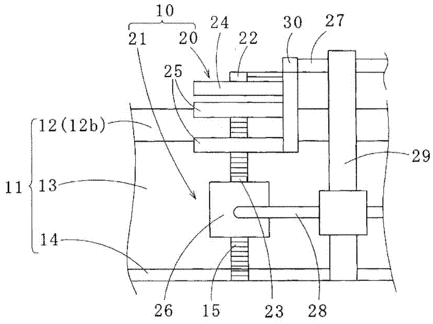
A device for cooling a welded rail section is provided with a first cooler for cooling a head section of the welded rail section, a second cooler for cooling a column section of the welded rail section, and a control unit for controlling the first cooler and the second cooler. The first cooler is provided with a first temperature detection section for detecting the temperature of the head section, and also with a first discharge section for discharging a first cooling fluid toward the head section. The second cooler is provided with a second temperature detection section for detecting the temperature of the column section, and also with a second discharge section for discharging a second cooling fluid toward the column section. The control section individually changes the kind, amount, and flow speed of the first cooling fluid and the second cooling fluid when the head section and the column section are cooled.

Description

technical field [0001] The present invention relates to a cooling device and cooling method of a rail welded part after rail welding. [0002] This application claims priority based on Japanese Patent Application No. 2009-079938 for which it applied in Japan on March 27, 2009, and uses the content here. Background technique [0003] The joint of the track is the most prone to damage and cost maintenance in the track. In addition, the joints of the rails are main sources of noise and vibration generated when trains pass. On the other hand, high-speed passenger railways and heavy-duty freight railways are being promoted both at home and abroad. Due to such a situation, the technique of manufacturing a long track with a total length of 200 m or more by continuous welding of the joints of the track has been widely used. [0004] As the main welding methods for track joints, there are flash butt welding (flash pad) welding (for example, refer to Patent Document 1), gas pressur...

Claims


Application Information

Patent Timeline
Patent Type & Authority Applications(China)
IPC IPC(8): B23K31/00B23K11/04B23K11/36E01B11/46B23K101/26
CPCB23K11/04B23K11/046B23K11/36E01B29/44C21D9/04C21D9/505B23K2101/26
Inventor 杉山诚司梶原贡狩峰健一
Owner NIPPON STEEL CORP
Learn More