
A Secondary-side Phase Shift Controlled Full-Bridge Converter

Active Publication Date: 2014-10-01
NORTHEASTERN UNIV LIAONING
View PDF3 Cites 0 Cited by
  • Summary
  • Abstract
  • Description
  • Claims
  • Application Information

AI Technical Summary

Problems solved by technology

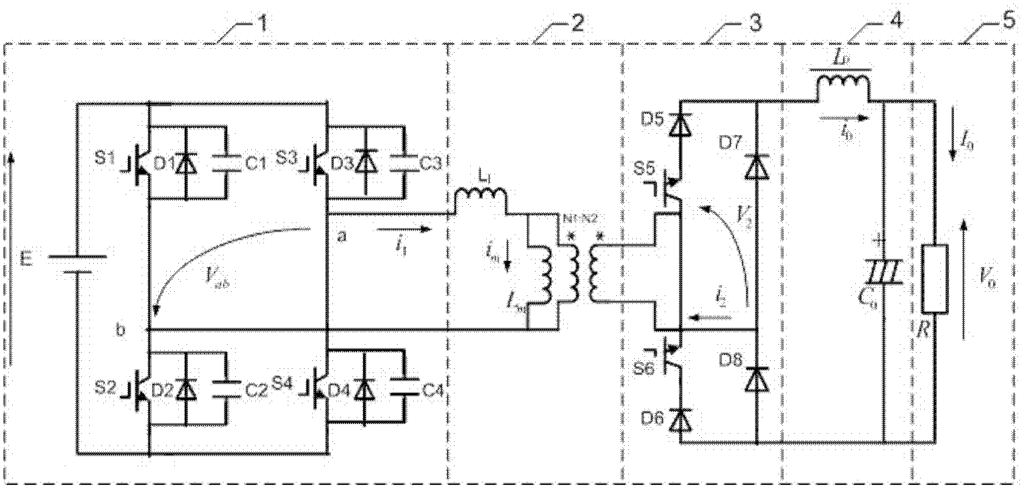
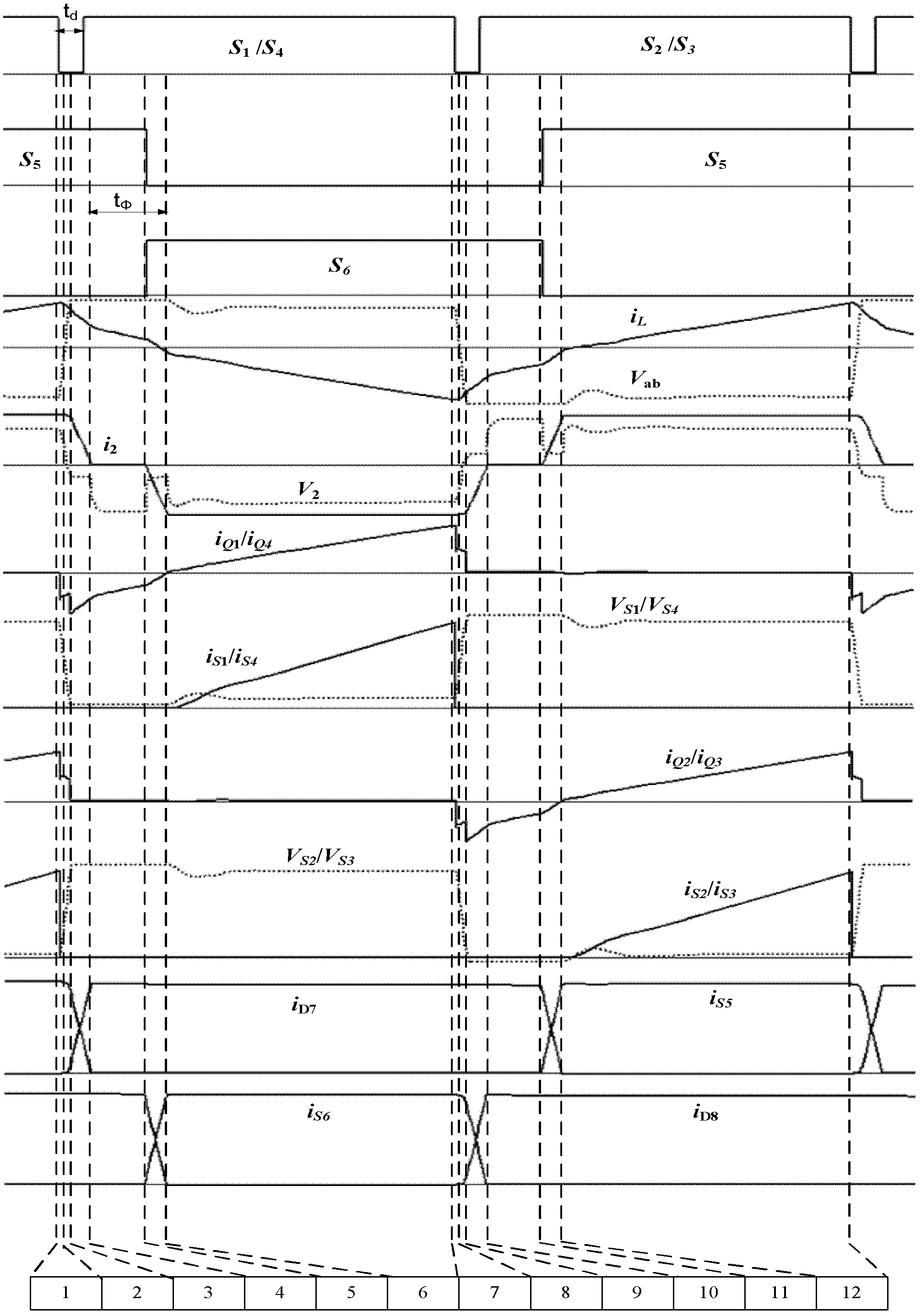
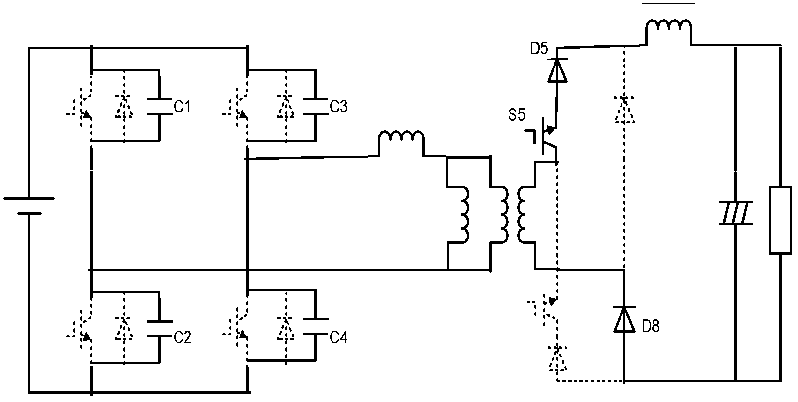
[0005] The working principle of the present invention is: when the full-bridge converter is working, the same group of switch tubes (S1 / S4, S2 / S3) on the primary side of the high-frequency transformer are simultaneously triggered to be turned on, which is realized with the assistance of parallel capacitance and transformer leakage inductance resonance Zero voltage and zero current are closed, and the corresponding switch tubes (S6 and S5) on the secondary side of the transformer are not closed temporarily to complete the phase shift control, and the secondary side of the transformer is in an open state. At this time, only a small excitation current flows through the primary side of the transformer, greatly The circulating current loss during the phase shifting process is reduced, and the simultaneous triggering of the two switching tubes of the same bridge arm solves the problem of the difficulty in realizing the zero voltage switch of the lagging arm. When the current on the secondary side increases, the DC power supply outputs power to the load. When the same group of switches on the primary side is disconnected, the parallel capacitance and transformer leakage inductance are used to resonate to achieve zero-voltage shutdown.

Method used


Image

  • A Secondary-side Phase Shift Controlled Full-Bridge Converter
  • A Secondary-side Phase Shift Controlled Full-Bridge Converter
  • A Secondary-side Phase Shift Controlled Full-Bridge Converter

Examples


Embodiment Construction

[0016] The present invention will be described in further detail below in conjunction with the accompanying drawings and embodiments.

[0017] The present embodiment is similar to the basic full-bridge conversion circuit in that it still consists of an inverter circuit (1), a high-frequency transformer (2), a rectification network (3), a filter circuit (4) and a load (5), Only the rectification network is improved: the fifth switching tube S5 and the sixth switching tube S6 are respectively connected in series at the two output ends of the secondary side of the transformer, as figure 1 As shown, among them, the inverter circuit (1) is composed of four switching tubes S1~S4 connected in series, and the switching tube S 1 The drain of the switch is connected to the positive pole of the DC bus, the source of the switch S1 is connected to the drain of the switch S2, the source of the switch S2 is connected to the source of the switch S4, the drain of the switch S3 is connected to ...


PUM


Abstract

The invention discloses a secondary side phase-shifting controlled full-bridge converter, belonging to the technical field of electric energy converters. The secondary side phase-shifting controlled full-bridge converter comprises an inverter circuit, a high-frequency transformer, a rectifier network, a filter circuit and a load, wherein the rectifier network is a bridge-type rectifier circuit comprising four diodes D5-D8. According to the secondary side phase-shifting controlled full-bridge converter disclosed by the invention, the rectifier network is improved; and two output ends of a secondary side of the transformer are respectively connected with a fifth switching tube S5 and a sixth switching tube S6 in series. The secondary side phase-shifting controlled full-bridge converter is suitable for high-voltage and high-power application occasions and can be used for realizing soft switching of all switching tubes and effectively inhibiting the voltage and current peaks of the switching tubes; in addition, by using secondary phase-shifting control of the transformer, the condition that exciting current flows through a circuit in the phase-shifting process only is realized. Therefore, circular current loss is reduced and the difficulty of realizing zero-voltage on-off of a lag bridge arm is overcome.

Description

technical field [0001] The invention belongs to the technical field of electric energy converters, in particular to a secondary-side phase-shift control full-bridge converter. Background technique [0002] Converters composed of single tubes are generally used in small and medium power applications. In medium and high power applications, a full bridge converter is generally used. The traditional phase-shifted zero-voltage pulse-width modulation DC-to-DC (DC / DC) full-bridge converter uses the leakage inductance of the transformer or the primary side series inductance and the parasitic capacitance of the power tube to realize the zero-voltage switching of the switch tube. However, the topology of traditional circuits also has its own shortcomings. For example, the realization of zero-voltage soft switching of the switch tube on the primary side of the transformer is based on the large circulation loss. Although the loss of the switch tube is reduced, the increase in the circu...

Claims


Application Information

Patent Timeline
Patent Type & Authority Patents(China)
IPC IPC(8): H02M3/335H02M7/5387
CPCY02B70/1491Y02B70/10
Inventor 褚恩辉张化光刘秀翀王琳候蕊
Owner NORTHEASTERN UNIV LIAONING
Learn More