High-precision method for detecting wave aberration of system

A detection method and wave aberration technology, applied in the field of optical detection, can solve problems such as system errors and affect detection accuracy, and achieve the effects of improving measurement accuracy, system luminous flux, and signal-to-noise ratio.

Inactive Publication Date: 2012-03-07
CHANGCHUN INST OF OPTICS FINE MECHANICS & PHYSICS CHINESE ACAD OF SCI
View PDF7 Cites 24 Cited by
  • Summary
  • Abstract
  • Description
  • Claims
  • Application Information

AI Technical Summary

Problems solved by technology

[0007] In order to solve the problem that the existing interferometry method causes systematic errors in the measurement results and affects the detection accuracy, this invention proposes a high-precision systematic wave aberration detection method that can calibrate the system errors to solve the problems existing in the current technology

Method used


Image

  • High-precision method for detecting wave aberration of system
  • High-precision method for detecting wave aberration of system
  • High-precision method for detecting wave aberration of system

Examples


Embodiment Construction

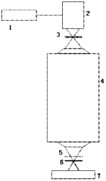
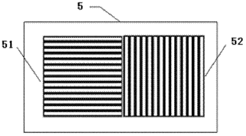
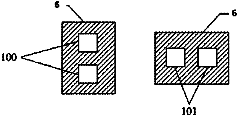
[0020] Such as figure 1 As shown, a high-precision system wave aberration detection method, the device used in the method includes: light source 1, illumination system 2, pinhole spatial filter 3, projection objective lens 4, beam splitting device 5, image plane spatial filter 6 and the image sensor 7, the steps of the wave aberration detection method are as follows:

[0021] Step 1) The light source 1 emits an illumination beam, and after entering the illumination system 2, the light intensity distribution and illumination mode are adjusted by the illumination system 2, and the outgoing beam passes through the pinhole spatial filter 3 and then diffracts to generate a beam of an ideal spherical wavefront; wherein the pinhole diameter d is less than the diffraction-limited resolution of the incident beam,

[0022] and satisfy the formula: d ≤ λ 2 NA l ...


PUM


Abstract

The invention discloses a high-precision method for detecting wave aberration of a system, belonging to the field of optical detection. The method comprises the following steps of: emitting lighting beams by a light source, and generating an ideal spherical wavefront beam through diffraction after entering into a lighting system and a spatial pinhole filter with pinholes; enabling incidence beamsto enter into a detected projection objective, enabling emergent beams with aberration information to generate interference after being diffracted by an optical grating and passing through the spatial filter, acquiring the emergent beams by an image sensor, and carrying out wave surface fitting to obtain an aberration difference; enabling the incidence beams to enter into the detected projection objective through radiating and rotating by 180 DEG to obtain two wavefront measurement results, separating non-rotational symmetry components in system errors by using the characteristic of the Zernike polynomial in a unit circle field, increasing two optical axis exterior point measurements, figuring out the system errors, and subtracting the system errors by a measured value to obtain the actual wave aberration of the detected projection objective. The method for calibrating the system errors of an interferometer in the invention can be used for calibrating the system errors caused by the interferometer and improving the measuring precision of the interferometer.

Description

technical field [0001] The invention belongs to the field of optical detection and relates to a high-precision systematic wave aberration detection method. Background technique [0002] The projection objective lens of lithography machine is the core component of the lithography part in the semiconductor manufacturing process. With the development of the semiconductor industry to a smaller line width scale, more and more stringent requirements are put forward for the performance of the lithography projection objective lens. Systematic wave aberration is one of the landmark indicators to evaluate the performance of projection objective lens of lithography machine. Whether the lithography machine can expose a characteristic linewidth of tens of nanometers depends largely on whether the system wave aberration of the projection objective can be controlled within a few nanometers. This requires the development and possession of sub-nanometer-level precision system wave aberratio...

Claims


Application Information

Patent Timeline
Patent Type & Authority Applications(China)
IPC IPC(8): G03F7/20G01M11/02
Inventor 向阳于长淞
Owner CHANGCHUN INST OF OPTICS FINE MECHANICS & PHYSICS CHINESE ACAD OF SCI
Why Eureka
Try Eureka