High-temperature tail-gas heat-recovering energy-saving device

A heat recovery and energy-saving device technology, applied in the energy industry, climate sustainability, lighting and heating equipment, etc., can solve the problem of small contact area between flue gas and water, and achieve heat pollution avoidance, energy-saving structure, and low cost Effect

Inactive Publication Date: 2012-03-14
浙江文国重工机械有限公司
View PDF9 Cites 3 Cited by
  • Summary
  • Abstract
  • Description
  • Claims
  • Application Information

AI Technical Summary

Problems solved by technology

The disadvantage of this structure is that the contact area between the exhausted flue gas and water is small, so only a small amount of heat in the flue gas is transferred to the water. In addition, this device can only be used in hot water boilers or steam boilers.

Method used


Image

  • High-temperature tail-gas heat-recovering energy-saving device
  • High-temperature tail-gas heat-recovering energy-saving device
  • High-temperature tail-gas heat-recovering energy-saving device

Examples


Embodiment Construction

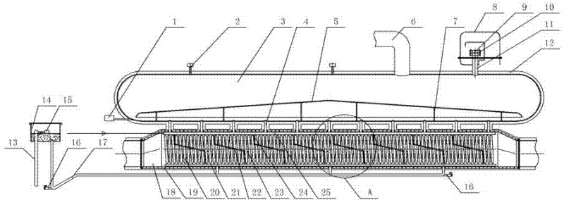
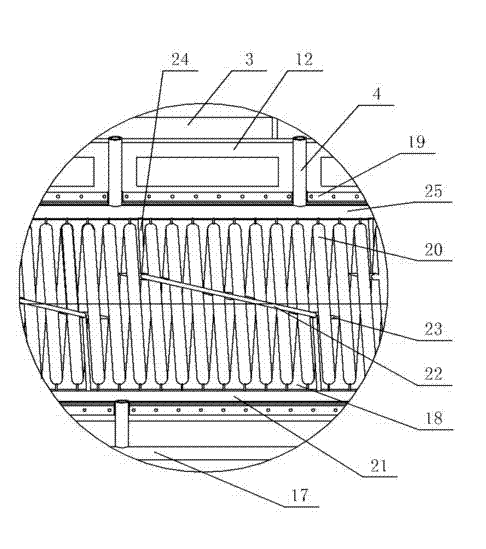
[0018] Such as figure 1 As shown, the present invention is a heat recovery energy-saving device for the high-temperature exhaust gas, which includes a flue 18 connected to the exhaust pipe, the flue 18 is tubular, and the high-temperature tail gas produced by the industrial boiler enters the flue through the exhaust pipe 18 in. The upper end of the air inlet of the flue 18 gradually rises from the outside to the inside, and the upper end of the air outlet of the flue 18 gradually lowers from the inside to the outside, so that the high-temperature exhaust gas can be buffered to a certain extent. The flue 18 includes a left half-shell and a right half-shell, and the left half-shell and the right half-shell are respectively provided with opposite flanges 19, which are fixed with bolts and nuts after the flanges 19 are docked. , the assembly of the flue 18 is completed. The bottom of the inner side of the flue 18 is axially equipped with an inlet water distribution pipe 21, and ...


PUM


Abstract

The invention relates to a high-temperature tail-gas heat-recovering energy-saving device, which comprises a flue, wherein the flue is abutted with a gas-discharging pipeline, the flue is pipe-shaped, an inlet-water flow-distributing pipe is axially distributed at the bottom at the inner side of the flue, the inlet-water flow-distributing pipe is communicated with a water tank through a water-transmitting pipe, a steam flow-distributing pipe is installed at the top at the inner side of the flue, a spiral heat-absorbing pipe is installed between the inlet-water flow-distributing pipe and the steam flow-distributing pipe, the lower end of each circle of the heat-absorbing pipe is communicated with the inlet-water flow-distributing pipe, and the upper end of each circle of the heat-absorbing pipe is communicated with the steam flow-distributing pipe; a steam-pot body is installed above the flue, a plurality of steam-spraying pipes which are communicated with an inner cavity of the steam-pot body are arranged on the steam flow-distributing pipe, and a steam-outlet pipeline is arranged above the steam-pot body. Through adopting the high-temperature tail-gas heat-recovering energy-saving device, not only can the thermal pollution formed by high-temperature tail-gas discharge be avoided, but also heat energy can be simultaneously recovered in the mode of steam, the high-temperature tail-gas heat-recovering energy-saving device has the advantages of low carbon, environmental protection, energy saving, simple structure and low cost, direct economic benefit can be brought, and the high-temperature tail-gas heat-recovering energy-saving device can be used for various industrial boilers which can generate the high-temperature tail gas.

Description

technical field [0001] The invention relates to a waste heat treatment device for tail gas discharge, in particular to a device for recovering and reusing heat in high-temperature tail gas. Background technique [0002] Industrial boilers will produce a large amount of high-temperature exhaust gas during use. If these high-temperature exhaust gases are discharged without treatment, it will seriously damage the surrounding ecological environment and cause thermal pollution. However, the cost of existing exhaust heat removal devices is generally high, so most small and medium-sized enterprises generally do not install them in order to save costs. In addition, the waste heat of the tail gas contains a large amount of thermal energy, and it is relatively wasteful to directly dispose of it. Therefore, people try to extract heat energy from the high-temperature tail gas. The "Boiler Chimney Waste Heat Recovery Device" published by the Chinese Patent Office on June 28, 2006, with ...

Claims


Application Information

Patent Timeline
Patent Type & Authority Applications(China)
IPC IPC(8): F22B1/18F22B37/42
CPCY02P80/15
Inventor 张宏生
Owner 浙江文国重工机械有限公司
Why Eureka
Try Eureka