Energy acquiring and electromagnetic triggering system of high-voltage thyristor valve bank

A high-voltage thyristor valve and electromagnetic triggering technology, which is applied in the direction of electromagnetic wave systems, electrical components, circuit devices, etc., can solve problems such as complex generation methods of high-power current sources, endangering the reliability of equipment systems, and easy generation of corona discharge, etc., to achieve The effect of simple structure, solving hidden troubles and low cost

Inactive Publication Date: 2012-03-14
HUBEI SANHUAN DEV
View PDF4 Cites 12 Cited by
  • Summary
  • Abstract
  • Description
  • Claims
  • Application Information

AI Technical Summary

Problems solved by technology

This energy harvesting method has complex circuits and high cost, and is generally only suitable for thyristor valves with a voltage level of 10KV and below.
Patent ZL01145559.4 introduces a multi-output isolated power supply for triggering thyristor valve strings. It is a typical circuit of this kind of energy harvesting method. The role of isolation energy harvesting requires a series of complex circuits such as secondary side circuits, auxiliary power circuits, and optical fiber transmission trigger signals, photoelectric conversion, and shaping and amplification on the TE board of the thyristor.
More importantly, this kind of multi-output isolated power supply is generally only suitable for application in TCR thyristor valve groups of 10KV and below. If it is applied to TCR thyristor valve groups of 35KV and above voltage, high-voltage cables and current transformers Corona discharge is likely to occur between the iron core and its secondary winding, which endangers the safety of the equipment and the reliability of the system.

Method used


Image

  • Energy acquiring and electromagnetic triggering system of high-voltage thyristor valve bank
  • Energy acquiring and electromagnetic triggering system of high-voltage thyristor valve bank
  • Energy acquiring and electromagnetic triggering system of high-voltage thyristor valve bank

Examples


Embodiment Construction

[0034] The technical solution of the present invention will be described in further detail below in conjunction with the accompanying drawings.

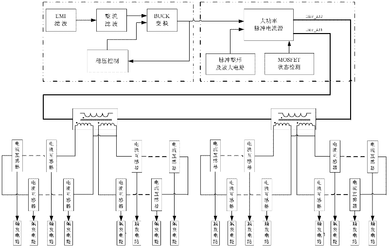
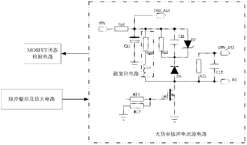
[0035] Such as figure 1 As shown, an energy harvesting and electromagnetic triggering system for a high-voltage thyristor valve group includes a pulse current source device for generating pulse current, a BUCK voltage stabilizing conversion device for providing voltage to the pulse current source, and a device for controlling the pulse current source. The isolation transformer device for isolating the generated pulse current, the feedthrough current transformer for transforming the pulse current isolated and output by the isolation transformer device, and the TCR thyristor valve group using the output signal of the feedthrough current transformer Triggered electromagnetic trigger device.

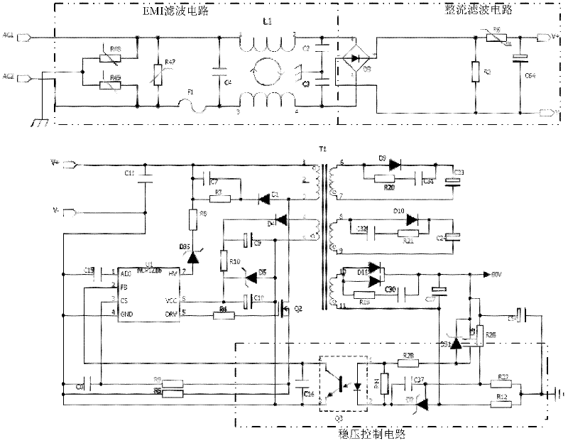
[0036] Such as figure 2 As shown, the BUCK voltage stabilization conversion device includes an EMI filter module for filtering the input 220V p...


PUM


Abstract

The invention discloses an energy acquiring and electromagnetic triggering system of a high-voltage thyristor valve bank. The system comprises a pulse current source device for generating power pulse current, a BUCK stable voltage transformation device for supplying a stable direct-current voltage to a pulse current source, an isolating transformation device for isolating the pulse current generated by the pulse current source, a straight through current transformer for transforming the pulse current isolated and output by the isolating transformation device and an electromagnetic triggering device for triggering the thyristor controlled reactor (TCR) thyristor valve bank by using the output signal of the straight through current transformer. The system realizes combination of energy acquiring and triggering functions, reduces the requirement for the isolated voltage of the current transformer, is suitable for triggering control of the TCR thyristor valve bank of 35KV and higher voltage level, and is mainly applied to reactive power compensation of power grids and certain industrial users with impact loads.

Description

technical field [0001] The invention belongs to the technical field of power electronics, and in particular relates to an energy harvesting and electromagnetic trigger system of a high-voltage thyristor valve group, which is suitable for the trigger control of a high-voltage TCR thyristor valve group, and is used for reactive power compensation of power grids and industrial users with impact loads . Background technique [0002] Modern society is inseparable from flexible AC transmission system, and SVC (Static Vat Compensator) and SVG (Static Var Generator) are the basic technology and key equipment of flexible AC transmission system. The high-voltage TCR (Thyristor Controlled Reactor) is the core device of the SVC, which consists of a thyristor valve group and a series inductor composed of multi-stage anti-parallel thyristor pairs connected in series. Usually, the amount of reactive current injected into the grid is controlled by controlling the conduction angle of the th...

Claims


Application Information

Patent Timeline
Patent Type & Authority Applications(China)
IPC IPC(8): H02J17/00H02M1/092H02J50/10
Inventor 毕平劲周俊李小芬罗运成
Owner HUBEI SANHUAN DEV
Why Eureka
Try Eureka