Control method for voltage-source-type unit power factor high-temperature superconducting energy storage converter

A technology of unit power factor and voltage source type, applied in the direction of DC power input conversion to DC power output, AC power input conversion to DC power output, output power conversion device, etc., can solve the problem of debugging difficulties, complex control circuits, Superconducting magnetic energy storage converter control method is difficult and other problems, to achieve the effect of strong control and signal processing capabilities

Active Publication Date: 2012-03-14
CHINA ELECTRIC POWER RES INST +1
View PDF3 Cites 33 Cited by
  • Summary
  • Abstract
  • Description
  • Claims
  • Application Information

AI Technical Summary

Problems solved by technology

In addition, when superconducting magnets are charging, resuming, and discharging, it is generally required that the DC bus voltage output be stable, the grid-side power change rapidly, the magnet energy storage respond quickly, and have a high switching frequency, etc. The study of flow controller control method brings difficulties
[0004] The control system of the traditional superconducting energy storage converter is mostly implemented by a single-chip microcomputer or a dedicated analog chip. The control circuit has disadvantages such as complex circuits, difficult debugging, poor anti-interference ability, and temperature drift.

Method used


Image

  • Control method for voltage-source-type unit power factor high-temperature superconducting energy storage converter
  • Control method for voltage-source-type unit power factor high-temperature superconducting energy storage converter
  • Control method for voltage-source-type unit power factor high-temperature superconducting energy storage converter

Examples


Embodiment Construction

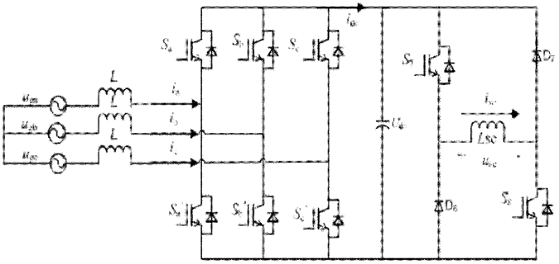
[0064] The circuit topology of the voltage source SMES converter is shown in the attached figure 1 As shown, it includes a four-quadrant three-phase fully-controlled voltage-type converter (VSC) and an "H" type bidirectional DC-DC chopper, and the two are connected with a DC capacitor. Therefore, the mathematical model of the voltage-type SMES can be simplified into two mathematical models: the mathematical model of the voltage-source converter and the mathematical model of the bidirectional chopper.

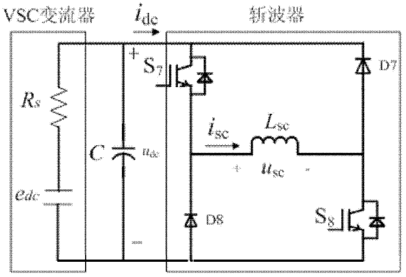
[0065] In the modeling process of the system, the VSC module can be approximately equivalent to a voltage source, therefore, the main circuit of the SMES converter is equivalent to the attached figure 2 . e dc is the equivalent voltage source on the DC side, R s is the internal resistance of the equivalent voltage source, i sc is the superconducting magnet current, i dc is the DC side current of the voltage source converter, u dc is the terminal voltage of DC bus capacito...


PUM


Abstract

The invention belongs to the field of applied superconducting power electronics, and in particular relates to a synchronizing current and voltage decoupling control method of a voltage-source-type unit power factor high-temperature superconducting energy storage system converter. The control method is characterized by comprising the following steps: designing a voltage outer ring control module at a direct-current side and a current inner ring control module at an alternating-current side respectively with respect to a mathematical model of a superconducting energy storage system converter under dq synchronizing rotary coordinates; controlling an 'H'-shaped bidirectional DC-DC (direct-current to direct-current) chopper based on an SPWM (sinusoidal pulse width modulation) technology by adopting a hysteresis loop PI current closed-loop control method in a charge mode and a hysteresis loop PI voltage closed-loop control method in a discharge mode; and finally implementing the synchronizing current and voltage double-fed control method of a voltage-source-type SMES (superconducting energy storage system) converter according to the active current requirement and the current value of a superconducting magnet under the power grid unit power factor. The control method provided by the invention has the advantages of multi-stage current decoupling control, rapid response speed, easy implementation of control algorithm and the like, and the method is especially suitable for the application occasions for improving the electricity energy quality of a power grid and inhibiting the low-frequency oscillation of a power system and the like.

Description

technical field [0001] The invention belongs to the field of applied superconducting power electronics, and in particular relates to a control method for a voltage-type high-temperature superconducting energy storage converter with a unit power factor based on DSP, in particular to a voltage source-type unit power factor superconducting energy storage converter Control Method of System Converter Background technique [0002] With the rapid development of modern power electronics technology, low-temperature refrigeration technology and high-temperature superconducting materials, high-temperature superconducting energy storage (HT-SMES) devices are gradually used in modern power systems to improve the quality of power grid power supply and suppress low-frequency oscillations in power systems , to improve the stability of the power system. Since the yttrium series (YBa 2 Cu 3 o 7 , YBa 2 Cu 4 o 8 ) and other second-generation high-temperature superconducting materials ha...

Claims


Application Information

Patent Timeline
Patent Type & Authority Applications(China)
IPC IPC(8): H02M7/797H02M3/155H02J3/24H02J3/18
CPCY02E40/10
Inventor 诸嘉慧杨斌丘明
Owner CHINA ELECTRIC POWER RES INST
Why Eureka
Try Eureka