Cross side dumping arrangement coordinated mode of rear conveyer of fully mechanized working face and support structure

A fully-mechanized caving face and conveyor technology, which is applied in mine roof support, cutting machinery, earthwork drilling and mining, etc., can solve the problems that the coal cannot be discharged in the transition section, and the recovery rate of the fully-mechanized caving face is restricted.

Active Publication Date: 2012-03-21
TIANDI SCI & TECH CO LTD +1
View PDF7 Cites 19 Cited by
  • Summary
  • Abstract
  • Description
  • Claims
  • Application Information

AI Technical Summary

Problems solved by technology

Due to the influence of the drive motor of the conveyor, the center distance of the front and rear conveyor heads and tails is inconsistent with the center distance of the middle section. Usually, 3 transition brackets are arranged in the transition section of the conveyor head and tail, and the transition brackets are mostly reversed. The four-link structure makes it impossible to discharge coal in the transition section, which restricts the improvement of the recovery rate of the fully mechanized caving face

Method used


Image

  • Cross side dumping arrangement coordinated mode of rear conveyer of fully mechanized working face and support structure
  • Cross side dumping arrangement coordinated mode of rear conveyer of fully mechanized working face and support structure
  • Cross side dumping arrangement coordinated mode of rear conveyer of fully mechanized working face and support structure

Examples


Embodiment Construction

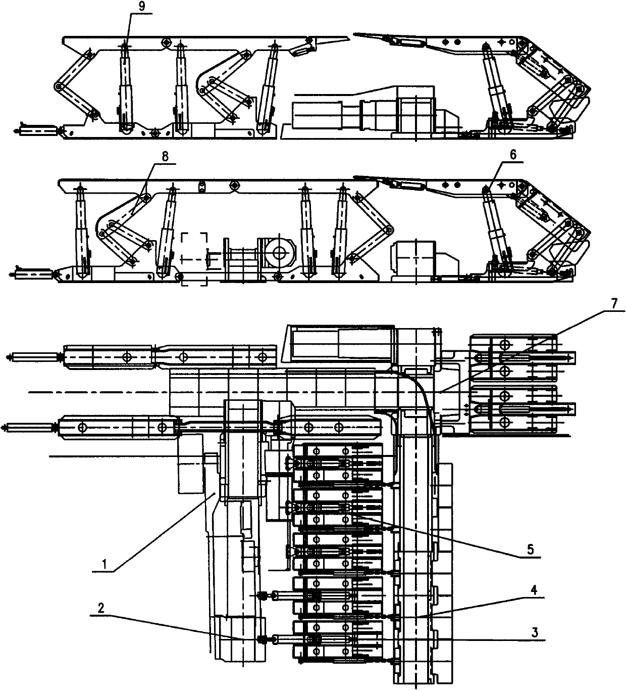
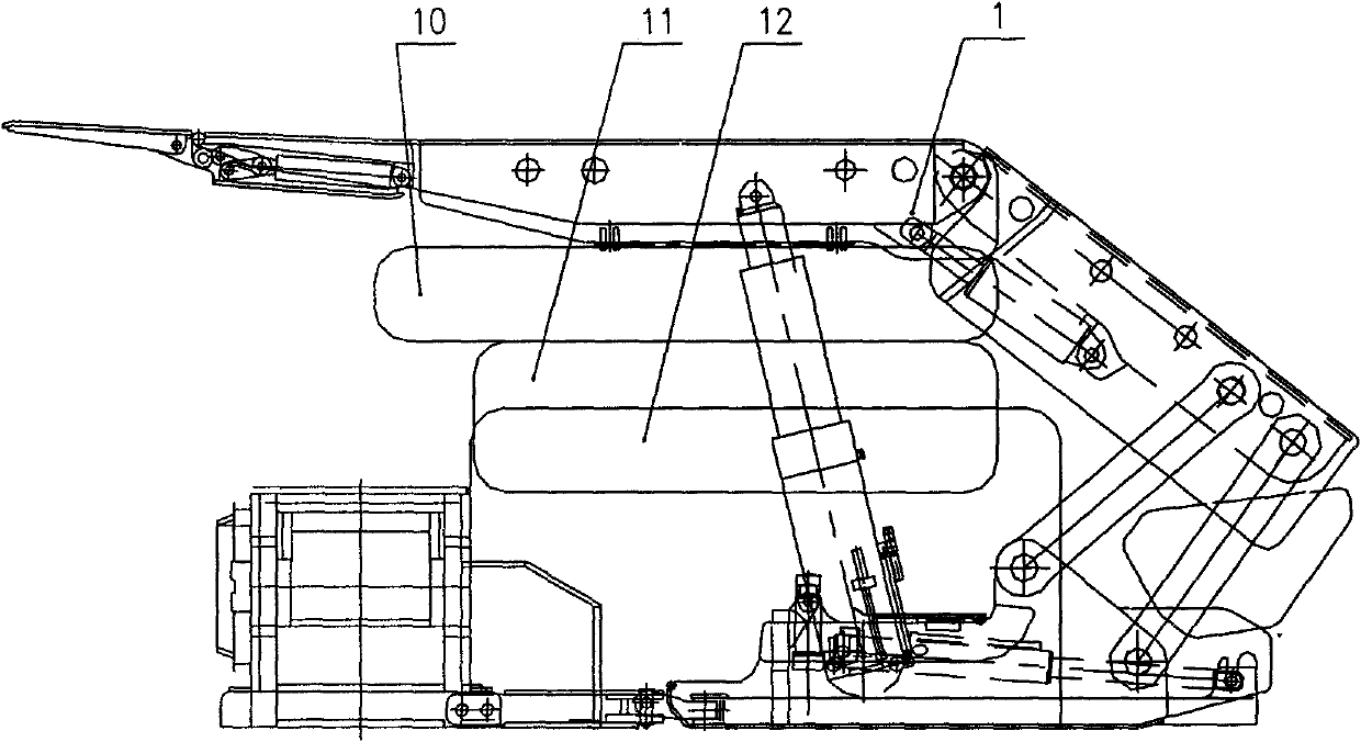
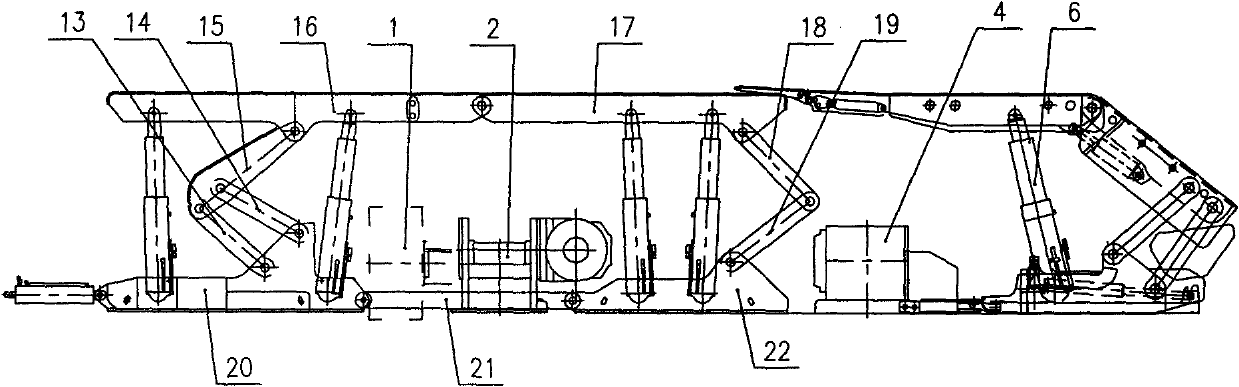
[0010] figure 1 The main equipment of the shown cross-side unloading layout fully mechanized caving face end supporting technology of the present invention includes a shearer (1), a front conveyor (2), a caving middle support (3), a rear conveyor (4 ), transition support (5), end of lane support (6), transfer machine (7), end support I (8) and end support II (9) etc.

[0011] In the fully-mechanized caving face, the supporting relationship between the shearer (1), the front conveyor (2) and the caving hydraulic support (3) is timely support, that is, after the shearer (1) cuts coal, the support (3); in the transition section of the front conveyor (2), the supporting relationship between the shearer (1), the front conveyor (2) and the caving transition bracket (5) is lag support, that is, the mining After the coal machine (1) cuts coal, the front conveyor (2) is pushed away earlier, and then the transition support (5) is pulled. Here, the unloading method of the rear conveyor...


PUM


Abstract

The invention discloses a new cross side dumping coordinated technology and a new supporting technology for an end region of a fully mechanized working face. The head of a rear conveyer is changed to a cross side dumping arrangement mode, and a motor of the rear conveyer is arranged in a smooth trough, so that the rear space of a transition support is not occupied any more, the center distance between the heads and the tails of the front and rear conveyers is consistent with the center distance of the middle sections, meanwhile, the unloading height of the conveyers is reduced, and the coal caving effect of the heads and the tails and the recovery rate of coal resources are further improved; and because the transition bracket is in the same structural form as a middle bracket, the category of hydraulic brackets of the working face can be reduced, and effective coal caving of the transition section of the top coal caving working face can be realized. A tunnel tail bracket is arranged at the rear part of a transferring machine, so that protection of the rear part of the transferring machine and smooth push of the transferring machine are realized; meanwhile, side guard plates which can be hinged are arranged on the lateral surfaces of the transferring machine, so that the rear gangue is prevented from falling into the tunnel tail bracket; end brackets are arranged at two sides of the transferring machine and have asymmetrical structures, a top beam has a step-type top beam structure, and the end brackets are matched with the tunnel tail bracket of the rear part, so that the stability of a top plate in the cross side dumping coordinated end region of the fully mechanized working face is maintained, and safe and efficiency recovery of the fully mechanized working face is realized.

Description

[0001] The invention relates to a design method of a hydraulic support, in particular to a three-dimensional design method of a hydraulic support in consideration of the dynamic influence of the surrounding rock of a coal mining face. technical background [0002] Comprehensive mechanized top-coal caving mining (abbreviated as fully-mechanized caving mining) is one of the efficient mining methods for thick coal seams in my country. The existing fully-mechanized caving working face is generally arranged in parallel with the driving parts of the front and rear conveyors, the motor of the driving part is parallel to the working face, and the unloading method of the conveyor and transfer machine is end unloading. Due to the influence of the drive motor of the conveyor, the center distance of the front and rear conveyor heads and tails is inconsistent with the center distance of the middle section. Usually, 3 transition brackets are arranged in the transition section of the conveyor...

Claims


Application Information

Patent Timeline
Patent Type & Authority Applications(China)
IPC IPC(8): E21C25/68E21C35/20E21D23/03E21D23/04
Inventor 王国法时成忠李明忠刘健刘壮王彪谋吴立忠胡万昌亓玉皓王春生冯立友任怀伟孟凡龙王建国辛家祥
Owner TIANDI SCI & TECH CO LTD
Why Eureka
Try Eureka