
Pneumatic energy machine system and pneumatic energy machine thereof

A technology of air energy machine and energy conversion system, which is applied in the direction of machines/engines, mechanical equipment, engine components, etc., which can solve the problems of waste of resources, inability to provide fresh air, waste of energy, etc., and achieve high conversion efficiency

Inactive Publication Date: 2012-03-21
冯袖幅
View PDF0 Cites 7 Cited by
  • Summary
  • Abstract
  • Description
  • Claims
  • Application Information

AI Technical Summary

Problems solved by technology

Since the gasoline engine can only use the potential energy generated during deflagration, the heat energy generated during deflagration will be lost through heat exchange with the air, resulting in waste of resources
[0005] In the above energy conversion process, because the oil and gas are burned in the combustion chamber, the fresh air in the combustion chamber cannot provide sufficient oxygen for the combustion of oil and gas due to the space limitation. Therefore, the incomplete combustion also causes a waste of energy.

Method used

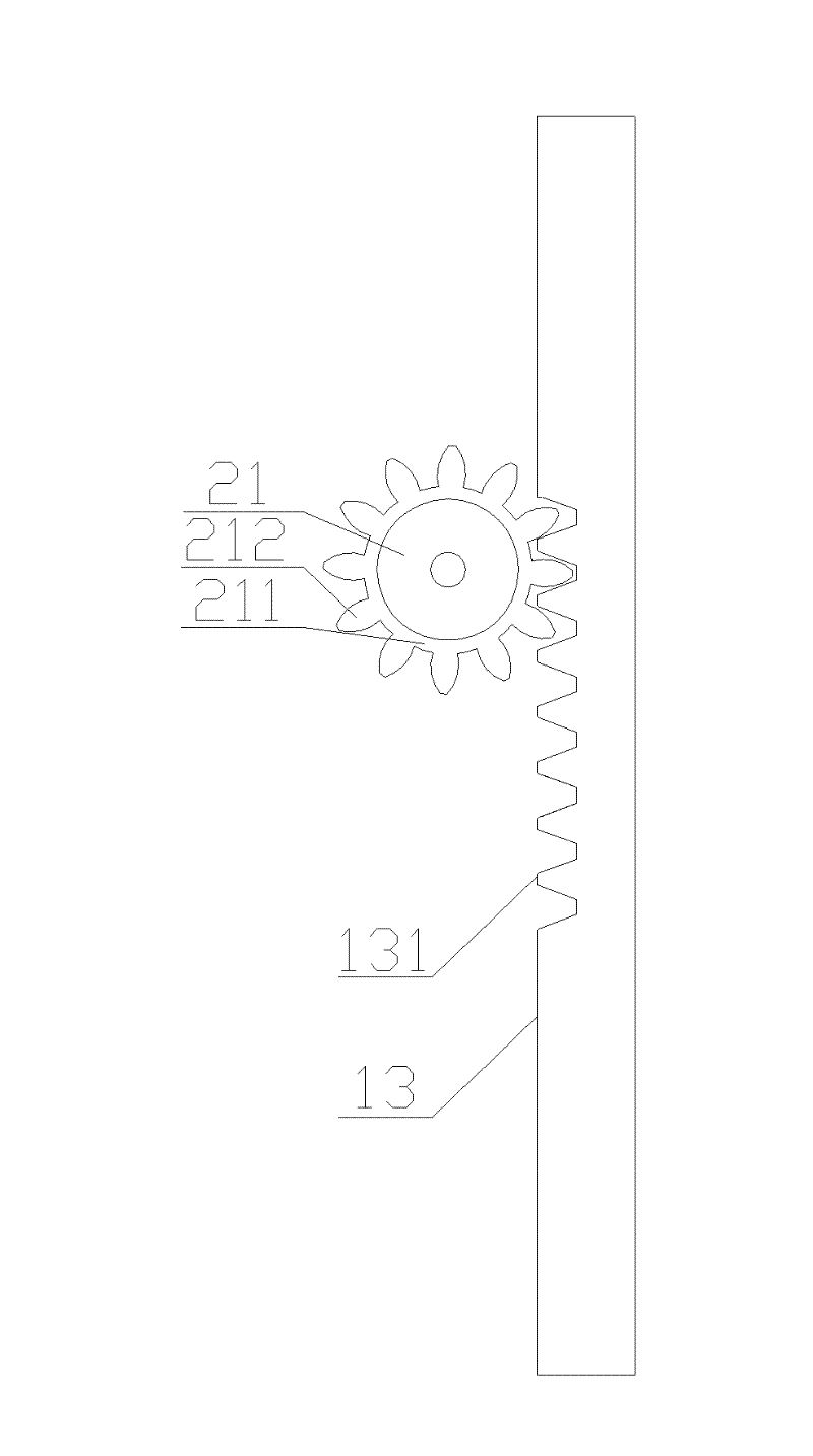
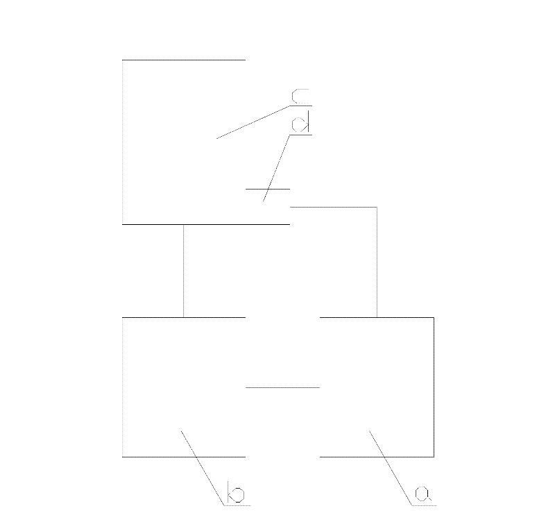

Image

  • Pneumatic energy machine system and pneumatic energy machine thereof
  • Pneumatic energy machine system and pneumatic energy machine thereof
  • Pneumatic energy machine system and pneumatic energy machine thereof

Examples


Embodiment Construction

[0031] The core of the present invention is to provide a gas energy machine system and its gas energy machine. The gas energy machine can use the atmosphere for energy conversion without generating any pollutants during the conversion process, and the invention has high conversion efficiency.

[0032] In order to enable those skilled in the art to better understand the technical solutions of the present invention, the present invention will be further described in detail below in conjunction with the accompanying drawings and specific embodiments.

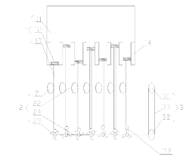
[0033] Please refer to figure 1 , figure 1 It is a schematic structural diagram of an air energy machine in an embodiment of the present invention.

[0034] The air energy machine a provided by the present invention is an energy conversion device, specifically a device for converting pressure energy into mechanical kinetic energy, including a pneumatic cylinder system 1 and an energy conversion system 2 .

[0035] The pneumatic c...


PUM


Abstract

The invention discloses a pneumatic energy machine which comprises a pneumatic cylinder system and an energy conversion system. The pneumatic cylinder system can convert pneumatic energy into kinetic energy of a piston through a pneumatic cylinder and the piston of the pneumatic cylinder system. The piston drives the energy conversion system to operate by the connection action of a connecting rod. The energy conversion system comprises a reversible driving wheel, a transmission shaft, a cam and a camshaft. The connecting rod drives the reversible driving wheel to rotate and outputs energy to the outside through the transmission shaft; and meanwhile, the output shaft drives the camshaft and the cam to rotate. The connecting rod is ejected back by the cam, so that the piston is reset; and then the next energy conversion operation is carried out. By the structure design of the pneumatic energy machine, atmosphere can be applied to carry out energy conversion. The pneumatic energy machine has high conversion efficiency, and no environment pollution is generated.

Description

technical field [0001] The invention relates to the technical field of power devices, in particular to an air energy machine system and the air energy machine. Background technique [0002] At present, among the energy conversion devices, the engine is the most well-known and widely used, and some other energy conversion devices, such as batteries, also have a vital impact on people's life and work. [0003] The engine is a device that converts the chemical energy generated when the fuel reacts into the kinetic energy of mechanical parts. According to the fuel used, the engine can be divided into gasoline engine and diesel engine. The operation process of the gasoline engine is briefly introduced below. [0004] In the prior art, a typical gasoline engine comprises a sleeve, a combustion chamber, a piston and a connecting rod. The piston seal is arranged in the sleeve and is slidably and sealingly connected with the sleeve; rod connected. When gasoline is sprayed into the ...

Claims


Application Information

Patent Timeline
IPC IPC(8): F01B9/04F01B1/02F01B25/16
Inventor 冯袖幅
Owner 冯袖幅
Learn More