Scale-span in situ micro-nano stretching/compressing hydraulic drive testing device under microscopic assembly

A driving test, micro-nano technology, used in measuring devices, using repetitive force/pulse force to test the strength and strength characteristics of materials, etc., can solve the problems of complex structure, poor compatibility, high cost, etc., to achieve small size and application range. Extensive, compact effects

Active Publication Date: 2012-03-21
中机试验装备股份有限公司
View PDF5 Cites 4 Cited by
  • Summary
  • Abstract
  • Description
  • Claims
  • Application Information

AI Technical Summary

Problems solved by technology

[0007] The purpose of the present invention is to provide a cross-scale in-situ micro-nano tensile / compression hydraulic drive test device for microscopic components, which solves the problems of high cost, large volume, complex structure and poor compatibility in the current technology, as well as existing experimental tests. The testing of the mechanical properties of the material and the observation of the micro-morphological changes of the specimen in the process of the equipment are independent, separate, and cross-scale issues, and then provide a cross-scale in-situ micro-nano stretching / compression hydraulic pressure under the microscopic components. Drive test device
The invention solves the problem that the performance test and the detection part of the microscopic shape of the current test device are mutually independent and separated into two processes in the test, and compensates the loading test process through the high-precision control algorithm of displacement and load and makes the test Data to be corrected

Method used


Image

  • Scale-span in situ micro-nano stretching/compressing hydraulic drive testing device under microscopic assembly
  • Scale-span in situ micro-nano stretching/compressing hydraulic drive testing device under microscopic assembly
  • Scale-span in situ micro-nano stretching/compressing hydraulic drive testing device under microscopic assembly

Examples


Embodiment Construction

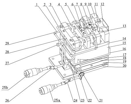
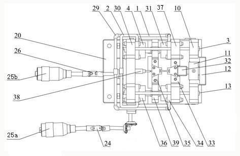
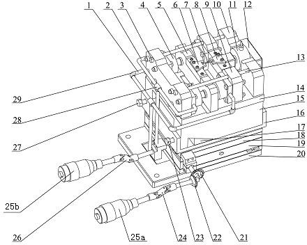
[0028] The detailed content of the present invention and its specific implementation will be further described below in conjunction with the accompanying drawings.

[0029] see figure 1 and figure 2 , the under-scale and in-situ micro-nano tension / compression hydraulic drive test device for micro-components of the present invention includes a hydraulic precision drive control unit, a test execution unit, a three-degree-of-freedom adjustment workbench, a test detection unit, a connection and a support unit; The hydraulic precision drive control unit and the test execution unit are: the output ends of the servo hydraulic cylinders I~IV4, 36, 31, and 34 are respectively connected to the mobile frame group 5, and the mobile frame group 5 is slidably connected to the base plate 14 , under the action of the external hydraulic servo control system, the servo hydraulic cylinders I, II4, 36 move in opposite directions to the servo hydraulic cylinders III, IV31, 34, and push the mobil...


PUM


Abstract

The invention relates to a scale-span in situ micro-nano stretching / compressing hydraulic drive testing device under a microscopic assembly, and belongs to machinery. The device comprises a hydraulic precision drive control unit, a testing execution unit, a three-degree-of-freedom (three-DOF) adjusting workbench, a testing detection unit and a connecting and supporting unit; the output ends of servo hydraulic cylinders I-IV are respectively connected with a mobile frame set, and the mobile frame set is connected with a substrate in a sliding manner; and the servo hydraulic cylinders I and II are respectively fixed on a front plate, the servo hydraulic cylinders III and IV are respectively fixed on a force testing frame set, and clamps I and II are respectively fixed above the mobile frameset and the testing frame set. The device has the advantages of small volume, light weight, high rigidity, compact structure, high testing precision, and capabilities of monitoring microscopic deformation and damage and fracture processes of test pieces on line, providing rich testing contents, acquiring important mechanical parameters of a material such as elastic modulus, yield limit, breaking strength and the like and acquiring the anti-fatigue performance of a sample.

Description

technical field [0001] The invention relates to the field of machinery, in particular to the field of material structure testing and in-situ observation and testing, especially to a micro-nano tensile / compression hydraulically driven test device under a microscopic component that is installed across a scale under a microscopic component. A hydraulic drive device for in-situ micro-nano solid materials for tensile / compression hydraulic drive tests and observation of microscopic crystal morphology deformation. It can directly correspond the microscopic deformation mechanism and mechanical properties of various materials, and reveal the relationship between the mechanical properties and macroscopic properties of materials across scales. Background technique [0002] In-situ nanomechanical testing refers to a mechanical testing technique that tests the mechanical properties of the specimen material at the nanometer scale, and monitors the microscopic deformation and damage of the...

Claims


Application Information

Patent Timeline
Patent Type & Authority Applications(China)
IPC IPC(8): G01N3/36G01N3/02
Inventor 赵宏伟张霖史成利胡晓利马志超黄虎王开厅
Owner 中机试验装备股份有限公司
Why Eureka
Try Eureka