Substrate cooling apparatus
A technology for cooling devices and substrates, applied in transportation and packaging, electrical components, semiconductor/solid-state device manufacturing, etc., can solve problems such as ineffective cooling, weak air flow, and inability to effectively take away substrates, so as to improve cooling efficiency and improve The effect of velocity
- Summary
- Abstract
- Description
- Claims
- Application Information
AI Technical Summary
Problems solved by technology
Method used
Image

Examples
no. 1 approach
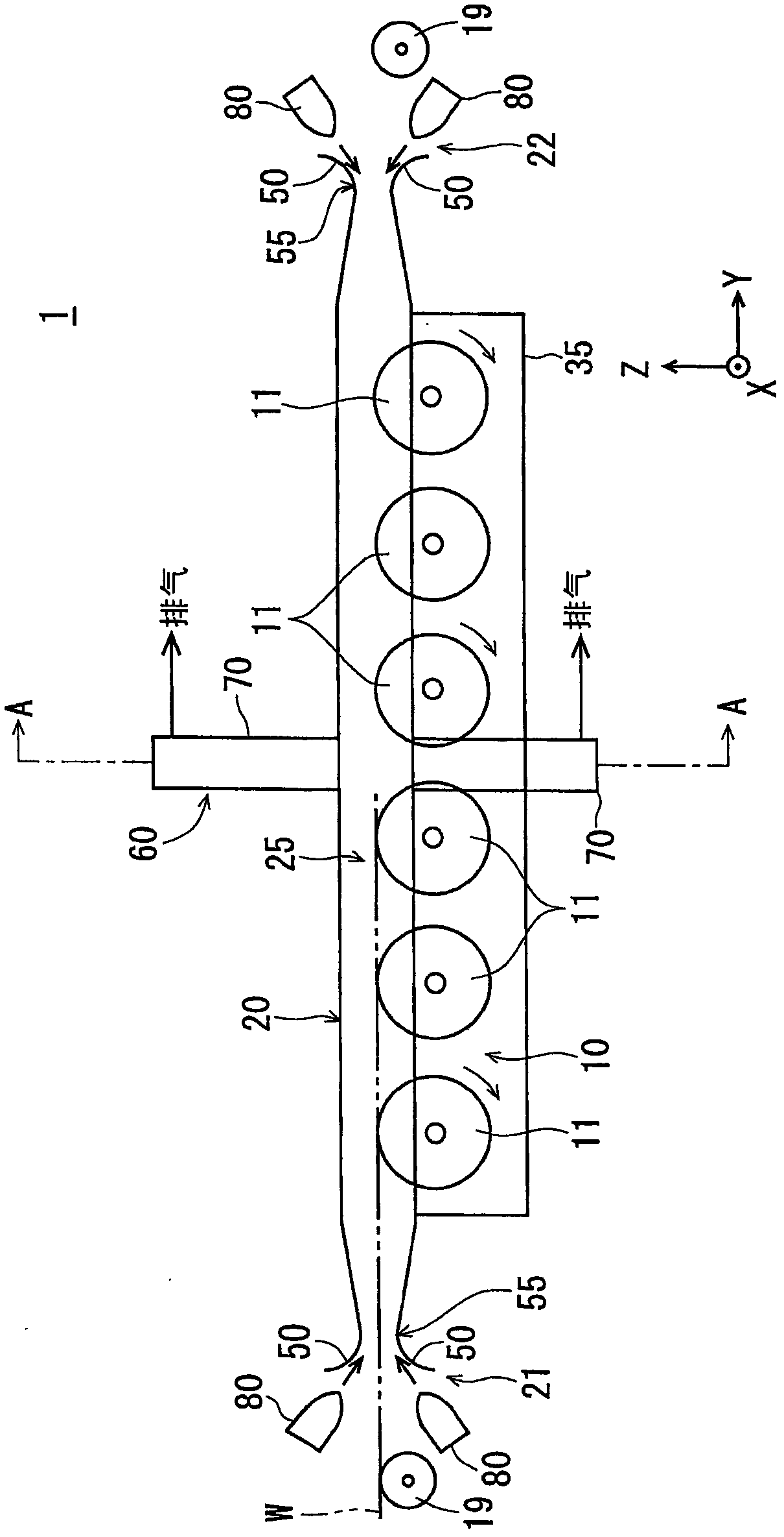
[0045] figure 1 It is a side view which shows the structure of the main part of the board|substrate cooling apparatus 1 which concerns on 1st Embodiment of this invention. exist figure 1 In each of the following figures, in order to clarify the directional relationship in the figures, the XYZ rectangular coordinate system with the Z-axis direction as the vertical direction and the XY plane as the horizontal plane is appropriately marked. In addition, in figure 1 In the drawings and the following figures, the dimensions of each part are exaggerated as necessary for easy understanding.
[0046] The substrate cooling apparatus 1 of the present invention is an apparatus for cooling a heat-processed substrate W (in this embodiment, a rectangular glass substrate for a liquid crystal display device) while conveying it. First, the overall schematic configuration of the substrate cooling device 1 will be described. The main structure of the substrate cooling device 1 includes a rol...
no. 2 approach
[0081] Next, a second embodiment of the present invention will be described. Figure 7 It is a figure which shows the board|substrate cooling apparatus of 2nd Embodiment. The substrate cooling apparatus according to the second embodiment is also an apparatus for cooling the heated substrate W while conveying it. In the first embodiment, the airflow forming mechanism 60 is constituted by the exhaust box 70 and the blower nozzle 80 , but in the second embodiment, the blower nozzle 80 is not provided, and the airflow forming mechanism 60 is constituted by only the exhaust box 70 . In other respects, the substrate cooling device of the second embodiment has the same structure as that of the first embodiment, and the same members as those of the first embodiment are Figure 7 marked with the same reference numerals.
[0082] In the substrate cooling apparatus of the second embodiment, since the blower nozzle 80 is not provided, an air flow is formed in the gas flow path 25 only b...
no. 3 approach
[0087] Next, a third embodiment of the present invention will be described. Figure 8 It is a figure which shows the board|substrate cooling apparatus of 3rd Embodiment. exist Figure 8 In , the same members as those in the first embodiment are given the same reference numerals. The substrate cooling apparatus according to the third embodiment is also an apparatus for cooling the heated substrate W while conveying it.
[0088] In the third embodiment, as in the first embodiment, the air flow forming mechanism 60 is constituted by the exhaust box 70 and the blower nozzle 80 . However, in the third embodiment, the exhaust port 71 and the exhaust box 70 are provided not at the central portion of the wind tunnel portion 20 but near the exit-side end portion. In addition, a pair of upper and lower buckets 50 is provided only at the entrance-side end of the wind tunnel 20 , and the blower nozzle 80 is provided only near the entrance-side buckets 50 . In other respects, the subst...
PUM
 Abstract
Description
Claims
Application Information
 - R&D
- Intellectual Property
- Life Sciences
- Materials
- Tech Scout
- Unparalleled Data Quality
- Higher Quality Content
- 60% Fewer Hallucinations
Browse by: Latest US Patents, China's latest patents, Technical Efficacy Thesaurus, Application Domain, Technology Topic, Popular Technical Reports.
© 2025 PatSnap. All rights reserved.Legal|Privacy policy|Modern Slavery Act Transparency Statement|Sitemap|About US| Contact US: help@patsnap.com