CdTe battery transition layer and preparation method thereof and CdTe battery

A transition layer and battery technology, applied in circuits, electrical components, photovoltaic power generation, etc., can solve the problems of rapid battery performance decay, unsuitability for large-scale industrial production, and complex transition layer preparation, so as to achieve stable battery performance and easy condition parameters The effect of simple control and preparation method

Inactive Publication Date: 2012-03-21
BYD CO LTD
View PDF1 Cites 7 Cited by
  • Summary
  • Abstract
  • Description
  • Claims
  • Application Information

AI Technical Summary

Problems solved by technology

[0006] The technical problem to be solved by the present invention is that the transition layer of the CdTe battery in the prior art causes rapid degradation of battery performance, and the preparation of the transition layer is complicated, which is not suitable for large-scale industrial production; thereby providing a battery with slow decay, simple preparation, and suitable Mass-produced CdTe battery transition layer

Method used


Image

  • CdTe battery transition layer and preparation method thereof and CdTe battery
  • CdTe battery transition layer and preparation method thereof and CdTe battery
  • CdTe battery transition layer and preparation method thereof and CdTe battery

Examples


preparation example Construction

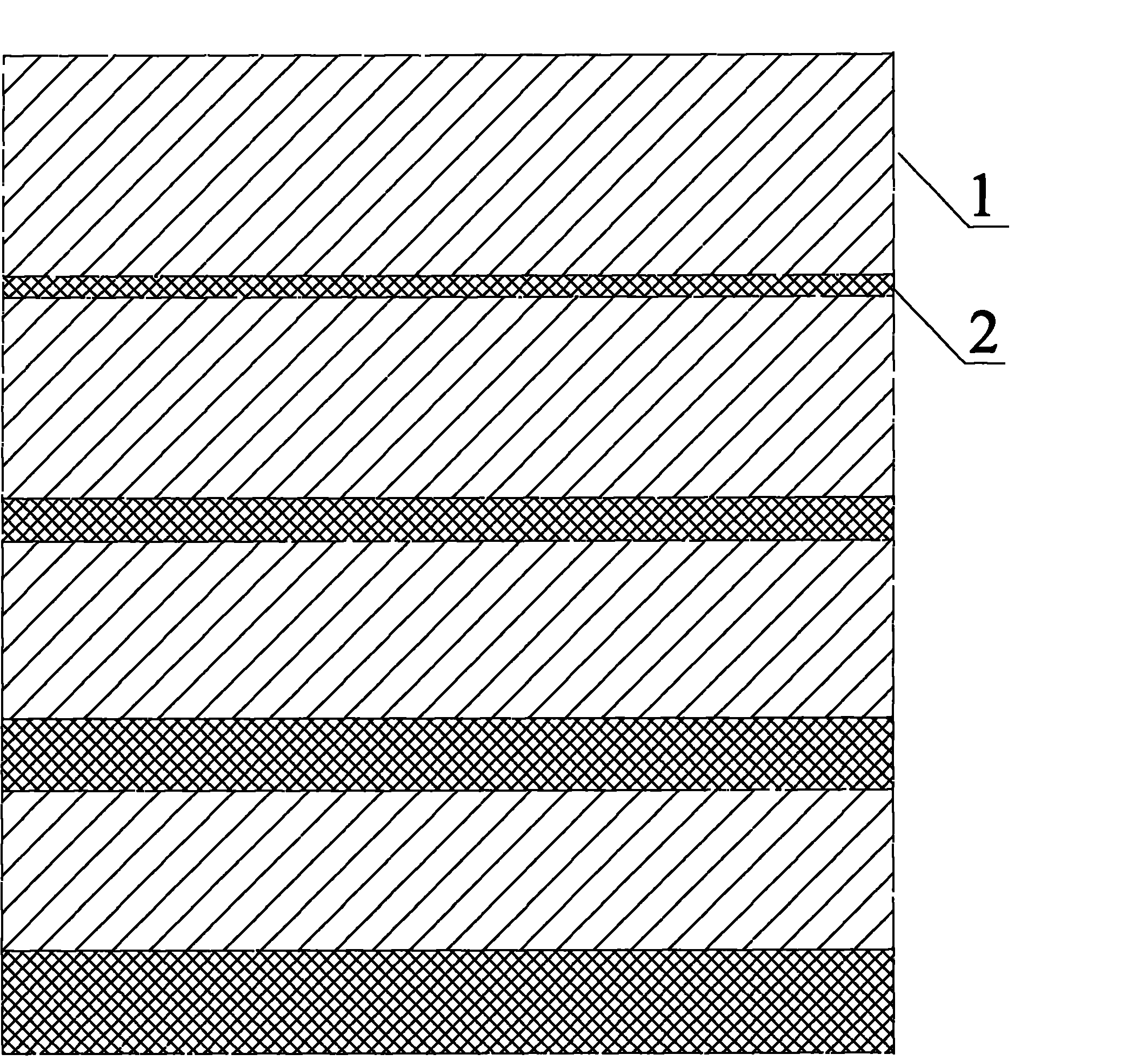
[0028] A preparation method for a transition layer of a CdTe battery, which comprises: first depositing a layer of ZnTe on the CdTe layer, and then alternately depositing a Cu layer and a ZnTe layer; In the range of ~40nm, the total thickness of the deposit is 25~120nm.

[0029] Wherein, the deposition can be realized by sputtering, electron beam evaporation and vapor deposition which are commonly used in the art.

[0030] The method of the present invention adopts single-source deposition, and the equipment is simple and the cost is cheap. At the same time, the atomic ratio of the product can be controlled by the thickness of the deposited film, which is relatively stable. The Cu layer is located behind the ZnTe film layer. By controlling the thickness of the ZnTe film layer, the diffusion depth of Cu can be controlled, so that it is not easy to diffuse into other film layers to form a wedge-shaped copper-doped transition. layer, which is beneficial to improve the short-circ...

Embodiment 1

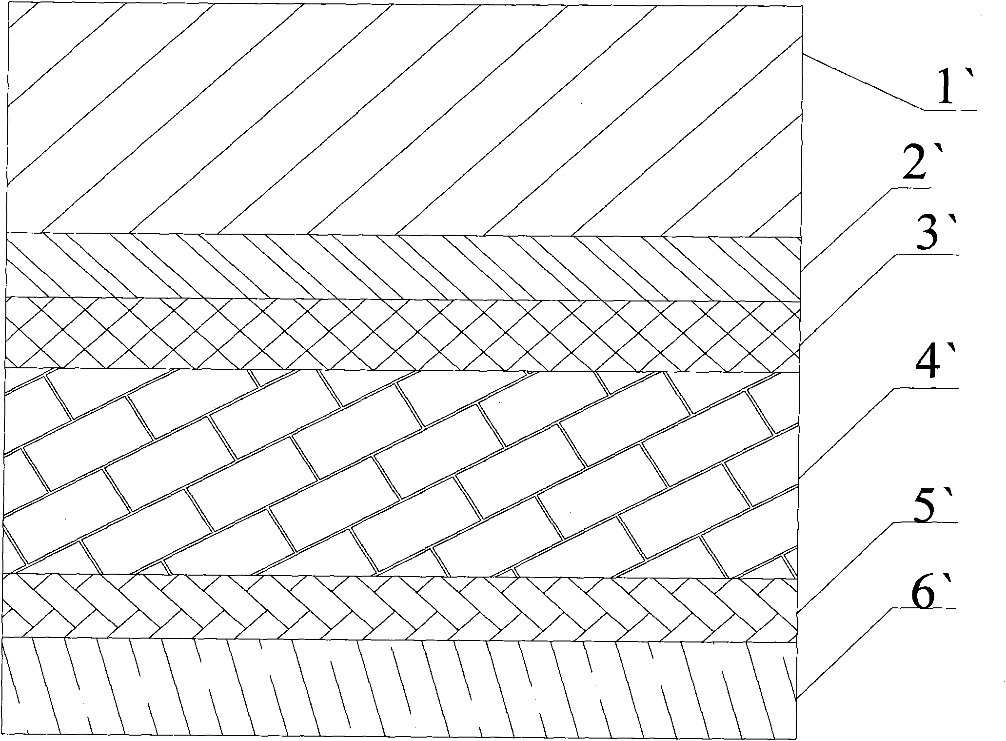
[0041] A CdTe solar cell, which includes a glass substrate, a transparent conductive layer, a CdS layer, a CdTe layer, a transition layer and a back electrode layer stacked in sequence;

[0042] The glass substrate is ultra-white glass with a thickness of 2mm; the transparent conductive layer is FTO with a thickness of 1um; the purity of the CdS layer is 5N and the thickness is 200nm; the purity of the CdTe layer is 5N and the thickness is 5um.

[0043] The transition layer is to deposit a 30nm ZnTe layer, a 4nm Cu layer, a 25nm ZnTe layer, and a 5nm Cu layer sequentially on the CdTe layer.

[0044] The back electrode layer is a Ni layer with a thickness of 200nm.

[0045] The battery is denoted as A1.

Embodiment 2

[0047] The difference from Example 1 is that the transition layer is sequentially deposited on the CdTe layer with a 25nm ZnTe layer, a 3nm Cu layer, a 20nm ZnTe layer, a 4nm Cu layer, a 15nm ZnTe layer, and a 5nm Cu layer.

[0048] Other parts are with embodiment 1.

[0049] The battery is denoted as A2.


PUM

PropertyMeasurementUnit
Thicknessaaaaaaaaaa
Thicknessaaaaaaaaaa
Total thicknessaaaaaaaaaa

Abstract

The invention belongs to the technical field of compound solar batteries, and in particular discloses a CdTe solar battery transition layer. The transition layer comprises a multilayer structure formed by alternately stacking ZnTe layers and Cu layers; the layer in contact with a CdTe layer in the multilayer structure is a first layer, and the first layer is the ZnTe layer; the thickness range of the ZnTe layers in the multilayer structure is 10 to 40 nanometers, and the thickness of the Cu layers in the multilayer structure is 1 to 10 nanometers; and the total thickness of the multilayer structure is 25 to 120 nanometers. The invention also discloses a preparation method of the CdTe battery transition layer and a CdTe battery using the transition layer. According to the transition layer of the CdTe battery, battery performance attenuation caused by Cu atom diffusion can be effectively inhibited, and the battery has stable performance. The preparation method of the transition layer is simple and can be used for large-scale streamline production. The condition parameters are easily controlled.

Description

technical field [0001] The invention belongs to the technical field of compound solar cells, and in particular relates to a CdTe battery transition layer, a preparation method thereof and a CdTe battery. Background technique [0002] CdTe is a compound semiconductor whose energy gap width is most suitable for photoelectric energy conversion. A solar cell made of this semiconductor is a device that directly converts light energy into electrical energy, and has a high theoretical conversion efficiency. Cadmium telluride is easy to deposit into large-area thin films, and the deposition rate is also high. Therefore, compared with silicon solar cells, the manufacturing cost of cadmium telluride thin-film solar cells is low, and it is a new type of solar cells with broad application prospects. [0003] Such as figure 1 As shown, the general structure of a CdTe solar cell is: from top to bottom, there are glass substrate 1`, transparent conductive film 2`, n-CdS layer 3`, p-CdTe...

Claims


Application Information

Patent Timeline
IPC IPC(8): H01L31/0224H01L31/0352H01L31/18
CPCY02E10/543H01L31/022425H01L31/073H01L31/1828Y02P70/50
Inventor 邓瑞周勇曹文玉
Owner BYD CO LTD
Why Eureka
Try Eureka