
Heating unit for bottom surface and conical surface of engine valve cap part and application method

An engine valve and heating device technology, which is applied in heat treatment furnaces, heat treatment equipment, furnaces, etc., can solve problems such as large deformation, inability to heat insulation and stress relief immediately, and unstable effects.

Active Publication Date: 2013-05-08
济南沃德汽车零部件有限公司
View PDF4 Cites 0 Cited by
  • Summary
  • Abstract
  • Description
  • Claims
  • Application Information

AI Technical Summary

Problems solved by technology

[0002] In the field of engine valves, alloy powder is generally surfacing on the cone surface of the product disc according to needs to improve the wear resistance life of the engine valve cone surface, but the weld layer after surfacing often leads to cracking due to the tensile stress
[0003] In the prior art, the heating methods to eliminate the tensile stress of the valve cone surface mainly include: (1) adopt heat treatment furnace heat preservation and annealing method, this method cannot immediately heat heat preservation and stress relief after surfacing welding, and the deformation is also large
(2) Coil induction heating method. The disadvantage of this method is that due to the large number of valve product models, correspondingly, many suitable induction coils should be made according to the product model. It is troublesome to adjust the tooling when replacing the product, and the effect of this method is not stable. ,Good times and bad
(3) After the surfacing of the conical surface, use the waste heat to quickly carry out forging and shaping. The disadvantage of this method is that there should be no delay after surfacing, otherwise the temperature will drop quickly and affect the forging effect. Only other methods can be used to reheat and surfacing. The equipment should be on the same site as the press, and the site area will be limited when the output is large

Method used


Image

  • Heating unit for bottom surface and conical surface of engine valve cap part and application method
  • Heating unit for bottom surface and conical surface of engine valve cap part and application method
  • Heating unit for bottom surface and conical surface of engine valve cap part and application method

Examples


Embodiment 1

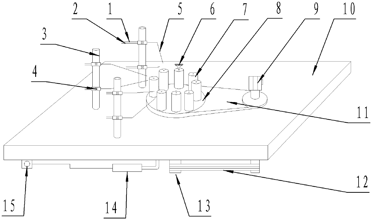
[0047] Embodiment 1, a heating device for the bottom surface and conical surface of an engine valve disc, is characterized in that it is mainly composed of a heater installed on the stand 10 and a valve fixing and rotating device,

[0048] Described heater is the oxyacetylene burner 5 that is fixed on the burner support,

[0049] The valve fixing and rotating device is composed of a sleeve 7 which is installed on the turntable 8 and can rotate with the turntable itself and rotates with the turntable, the sleeve self-rotating drive device and the turntable rotation drive device, and the valve 6 is inverted in the sleeve.

Embodiment 2

[0050] Embodiment 2, a heating device for the bottom surface and conical surface of the engine valve disc, is characterized in that: it is mainly composed of a heater installed on the stand 10 and a valve fixing and rotating device,

[0051] Described heater is the oxyacetylene burner 5 that is fixed on the burner support,

[0052] The valve fixing and rotating device is composed of a sleeve 7 which is installed on the turntable 8 and can rotate with the turntable itself and rotates with the turntable, the sleeve self-rotating drive device and the turntable rotation drive device, and the valve 6 is inverted in the sleeve.

[0053] The heater includes three burner supports 9 standing on the stand, and two sets of oxyacetylene burners arranged up and down are fixed by burner fixing sleeves 4 on each support. Oxygen port 1 and acetylene gas port 2 are installed on the burner

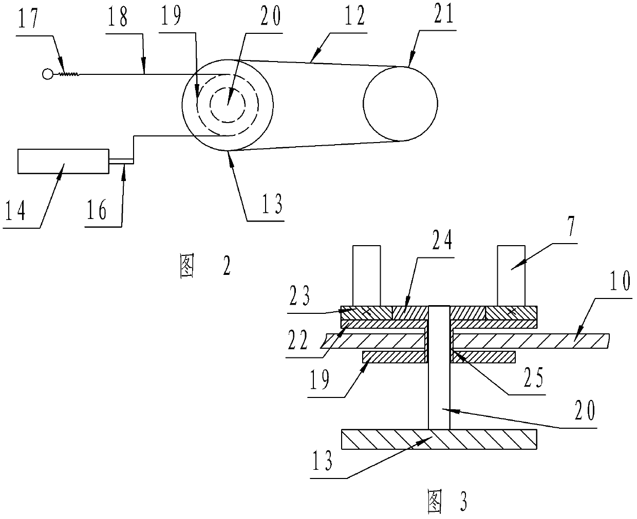
[0054]The sleeve self-rotating driving device includes a sleeve gear 23 fixed on the bottom of the slee...

Embodiment 3

[0056] Embodiment 3, using the method of the present invention to eliminate the tensile stress of the valve disc cone surface and form positive pressure, mainly includes the following steps,

[0057] (1) Make the oxyacetylene flame burn stably, and the power supply of the device work stably;

[0058] (2) Insert the engine valve into the valve sleeve, the sleeve rotates continuously driven by the servo motor, and the valve rotates continuously driven by the sleeve;

[0059] (3) Make the oxyacetylene flame heat the bottom surface and the conical surface of the valve at the same time, the valve is heated rapidly, and the temperature is measured with an infrared thermometer. When the stress relief temperature reaches 900-1000°C, turn the turntable to move the valve out of the heating zone;

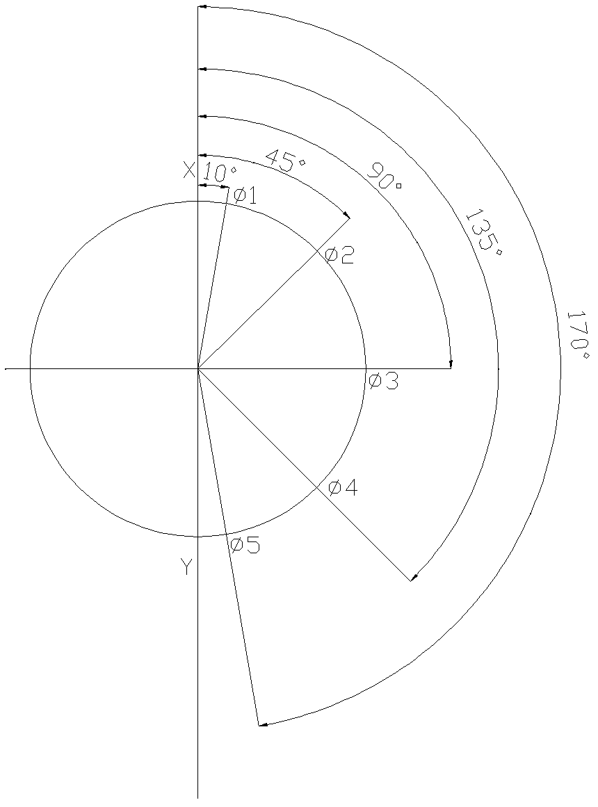
[0060] (4) The turntable rotates regularly under the action of the cylinder controlled by the time relay,

[0061] (5) When the valve is heated to the stress-relief temperature, the conical s...


PUM


Abstract

The invention discloses a heating unit for a bottom surface and a conical surface of an engine valve cap part and an application method, belongs to a heat treating device, and particularly relates to a heating source taking oxyacetylene flame as a heat source. The heating unit is characterized by mainly comprising a heater arranged on a rack and a valve fastening and a rotating device, wherein the heater is an oxyacetylene burner nozzle fixed on a burner nozzle support; and the valve fastening and the rotating device is composed of a sleeve which is arranged on a turnplate and can automatically rotate and rotate along with the turnplate, a sleeve self-rotating driving device and a turnplate rotating driving device. The heating unit provided by the invention has the beneficial effects that the heating unit can rapidly and conveniently heat the bottom surface and the conical surface subjected to overlaying, of the valve cap part and conveniently control heating time and temperature, the volume of equipment is small so as facilitate connection with a next step process, and the equipment is conveniently used for eliminating tension stress generated by overlaying of the valve.

Description

technical field [0001] The invention belongs to a heat treatment device, in particular a heating device using an oxyacetylene flame as a heat source, and a process method for forming the conical surface compressive stress of an engine valve disk using the same. Background technique [0002] In the field of engine valves, alloy powder is generally surfacing on the cone surface of the product according to needs to improve the wear resistance life of the engine valve cone surface, but the welding layer after surfacing often leads to cracking due to the tensile stress. [0003] In the prior art, the heating methods for eliminating the tensile stress of the valve cone surface mainly include: (1) heat treatment furnace heat preservation and annealing method is adopted. This method cannot immediately heat heat heat preservation to relieve stress after surfacing welding, and the deformation is also large. (2) Coil induction heating method. The disadvantage of this method is that due...

Claims


Application Information

Patent Timeline
Patent Type & Authority Patents(China)
IPC IPC(8): C21D1/52C21D9/00
Inventor 董兵李松岩肖学林陈雪萍聂元龙吕文清曲文强陶子祥
Owner 济南沃德汽车零部件有限公司
Learn More