

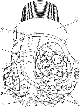
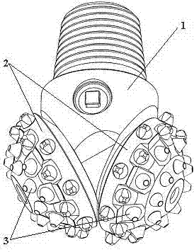
Compound bit formed by PDC (polycrystalline diamond compact) bits and rotary cutting bit
A compound drill bit and drill bit technology, which is applied in construction and other directions, can solve the problems of accelerated wear speed, fast wear speed, wear and tear, etc., and achieve the effect of improving cutting ability, good dynamic performance, and improving bearing structure
- Summary
- Abstract
- Description
- Claims
- Application Information
AI Technical Summary
Problems solved by technology
Method used
Image

Examples
Embodiment 1
[0062] When the rotary cutting drill bit of the present invention , ,diameter , the drilling speed is , the materials used in the experiment were Hongya stone: , green sandstone: During the experiment, rock cuttings were collected, the difficulty of rock breaking and vibration were analyzed, the wear marks and directions of cutting teeth were checked, and the wheel body speed ratio of the cone and the drill bit was calculated.
[0063] The results of the examples and the theoretical calculations also show that: under the corresponding parameter conditions in Example 1, the wheel body speed ratio is less than 1, and in this example it is less than 0.55; the harder the lithology, the higher the cone speed, and the higher the wheel body speed ratio.
Embodiment 2
[0065] when gear 2 , ,diameter , the drilling speed is , the materials used in the experiment are Hongya stone: , green sandstone: During the experiment, rock cuttings were collected, the difficulty of rock breaking and vibration were analyzed, the wear marks and directions of cutting teeth were checked, and the wheel body speed ratio of the cone and the drill bit was calculated.
[0066] Embodiment result and theoretical calculation show simultaneously: corresponding , the harder the lithology, the lower the speed of the cone, and the speed ratio of the wheel body is smaller than the value corresponding to Example 1.
[0067] Comprehensive comparative analysis of the above implementation results can be obtained: the cutting teeth of the rotary cutting drill bit in the composite drill bit of the present invention break rocks in a rotary cutting mode, have better dynamic performance, uniform wear, improved bearing working conditions, long service life of the drill b...
PUM
 Abstract
Description
Claims
Application Information