
Lubricating structure of timing chain system of engine

A lubricating structure and engine technology, which is applied in the direction of engine lubrication, engine components, valve accessories, etc., can solve the problems of no lubrication, increased friction of chains, sprockets and guide rails, etc., and achieve the effect of reducing running time and simple structure

Inactive Publication Date: 2012-04-04
CHONGQING CHANGAN AUTOMOBILE CO LTD
View PDF5 Cites 15 Cited by
  • Summary
  • Abstract
  • Description
  • Claims
  • Application Information

AI Technical Summary

Problems solved by technology

Once the engine starts, it takes a long time for the oil to reach the sprocket, which will cause the chain to run without lubrication for a period of time, which will increase the friction of the chain, sprocket and guide rail

Method used


Image

  • Lubricating structure of timing chain system of engine
  • Lubricating structure of timing chain system of engine
  • Lubricating structure of timing chain system of engine

Examples


Embodiment Construction

[0016] The present invention will be further described below in conjunction with the accompanying drawings.

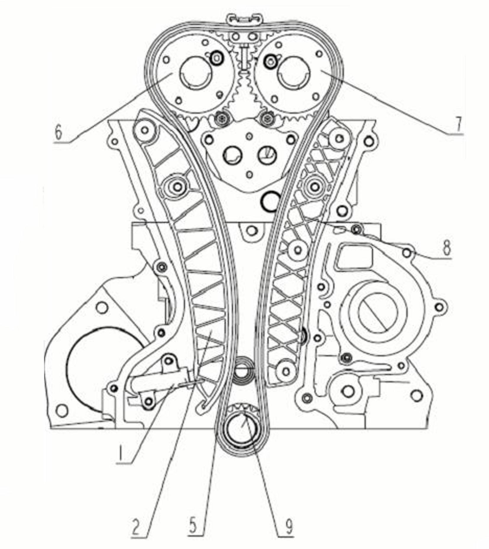
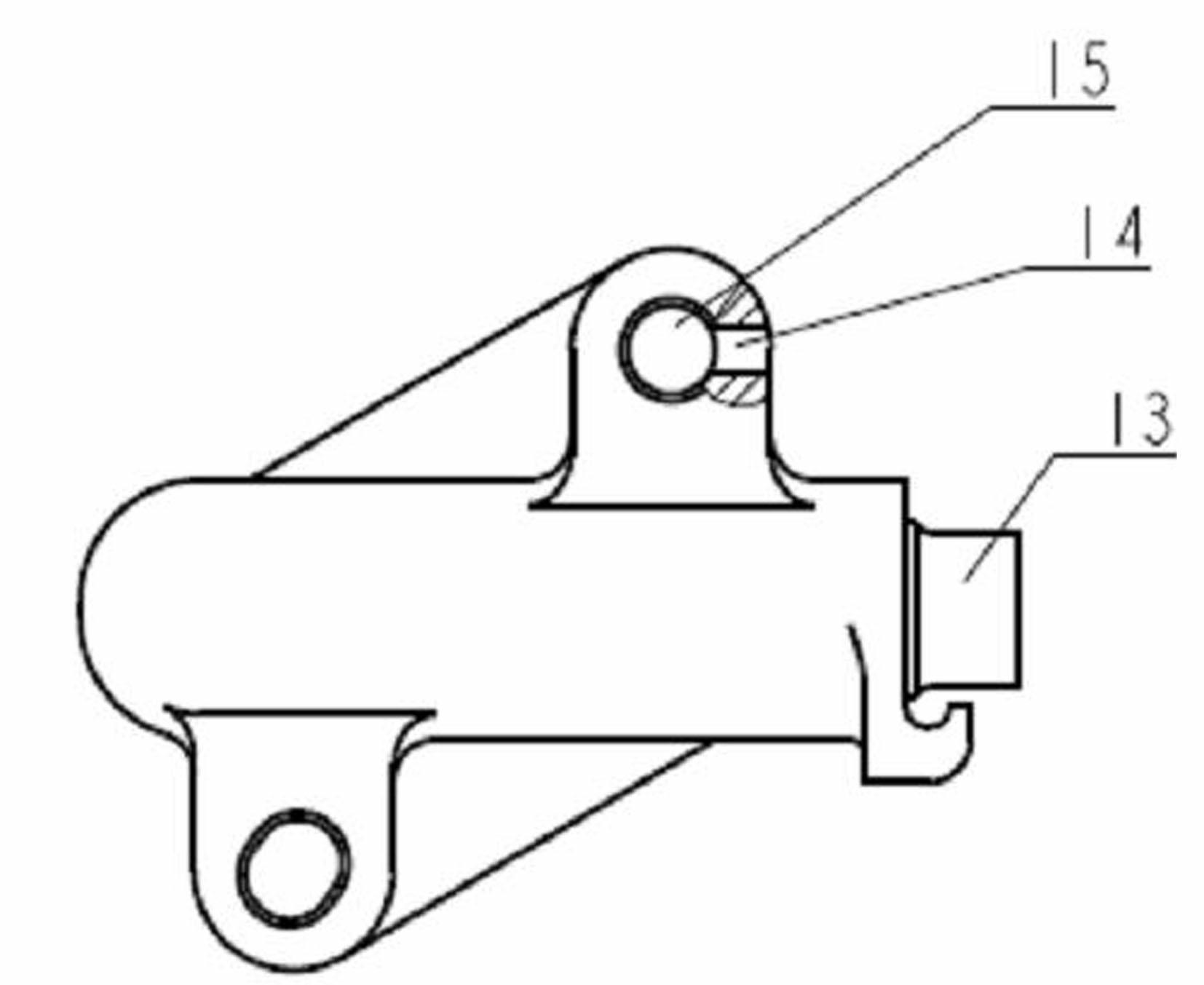
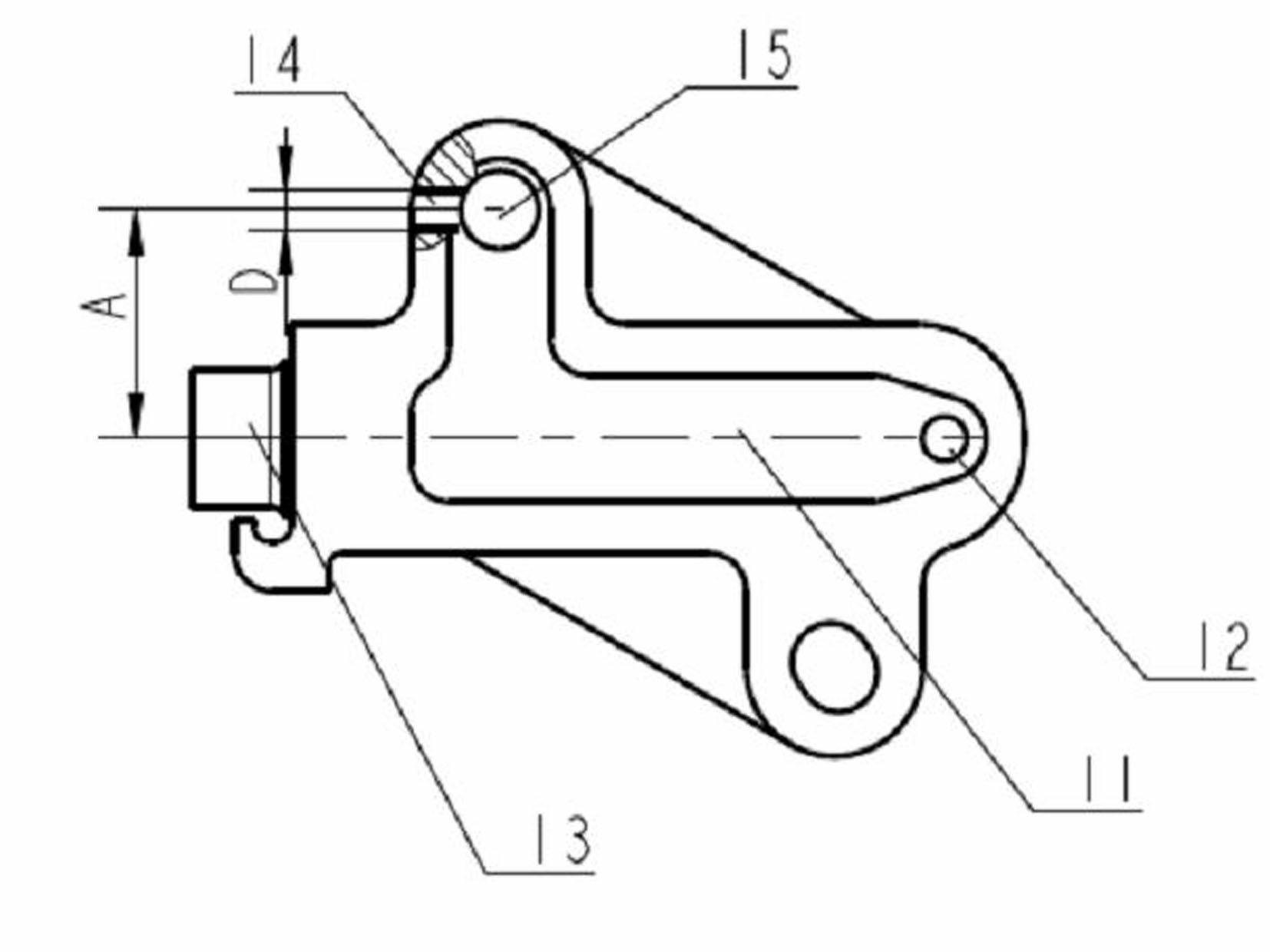
[0017] Such as figure 1 As shown, the lubrication mechanism of the timing chain system mainly involves the hydraulic tensioner 1, the timing chain moving rail assembly 2 and the timing chain assembly 5. The entire timing chain system is mounted on the front of the engine. The moving rail assembly 2 is installed on the cylinder head 10 , and the hydraulic tensioner 1 is installed on the cylinder body 20 . The oil from the oil channel is guided by the oil groove 11 on the tensioner to introduce the oil into the oil inlet 12 of the tensioner, forming oil pressure, pushing the piston 13 to move, and driving the moving rail assembly 2 to tighten the timing chain 5 .

[0018] By calculating the relationship between the oil pressure and the spatial position, an oil injection hole 14 with a smaller diameter is opened on the bolt mounting bracket on the upper part of the tens...


PUM


Abstract

The invention provides a lubricating structure of a timing chain system of an engine. The lubricating structure comprises a hydraulic tensioner, a timing chain movable rail assembly and a timing chain assembly, wherein an oil spray hole is formed in the hydraulic tensioner; the oil spray hole is connected with an oil groove in the hydraulic tensioner through a bolt through hole of the hydraulic tensioner; meanwhile, a through hole which is opposite to the oil spray hole is formed in the timing chain movable rail assembly in the transverse direction, and engine oil which is sprayed out flows to the timing chain assembly through the through hole in the timing chain movable rail assembly. The lubricating structure has the advantages that: by using an oil storage function of the hydraulic tensioner, timely lubrication of a timing chain of the engine can be effectively guaranteed, the quantity of oil ducts of oil filling holes in a cylinder body can be reduced, and the lubricating structure of the timing chain system is simplified.

Description

technical field [0001] The invention relates to a lubricating structure of an engine, in particular to a novel lubricating timing chain system lubricating structure composed of an engine timing chain hydraulic tensioner and a timing chain moving rail assembly. Background technique [0002] The friction of each kinematic pair of the engine timing chain system is very large, and sufficient lubrication is required to ensure the performance and life of the timing chain system. The lubrication of the traditional engine timing chain is through a special drain hole drawn from the upper cylinder head or cylinder block, and slowly flows along the outer surface of the cylinder head and cylinder body to the sprocket installed on the crankshaft under the action of gravity. The chain is lubricated through the engagement of the sprocket and the chain, and the lubricating oil is transmitted to other parts of the timing chain system through the chain. Due to the consideration of the oil pr...

Claims


Application Information

Patent Timeline
IPC IPC(8): F01M9/10F01M1/08F16H7/08
Inventor 李春成卫国苏继才
Owner CHONGQING CHANGAN AUTOMOBILE CO LTD
Learn More