Array substrate, fabricating method for same and liquid crystal display panel
A technology for array substrates and display areas, which is applied in semiconductor/solid-state device manufacturing, instruments, semiconductor devices, etc., can solve the problems of display area 320 size limitation and cannot be further enlarged, and achieve improved utilization, area saving, and crosstalk reduction Effect
- Summary
- Abstract
- Description
- Claims
- Application Information
AI Technical Summary
Problems solved by technology
Method used
Image

Examples
no. 1 example
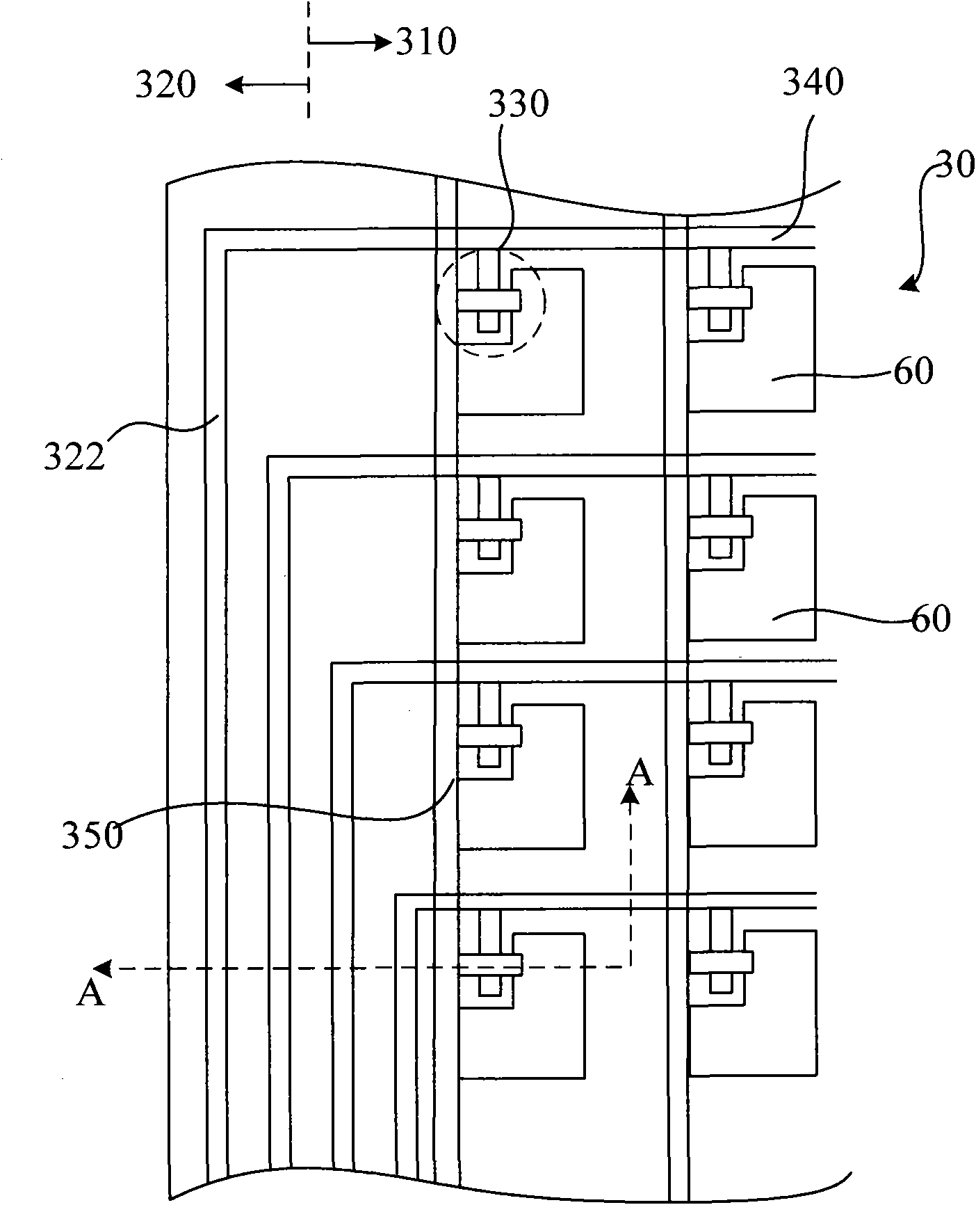
[0063] refer to Figure 5 , is a schematic top view structure diagram of the array substrate according to the first embodiment of the present invention.
[0064] The array substrate is divided into a display area and a frame area surrounding the display area. To simplify the illustration, Figure 5 Only a schematic top view of a part of the display area is shown in . The display area includes: a glass substrate; multiple scanning lines on the glass substrate: scanning line 101, scanning line 103, scanning line 105, etc., multiple data lines: data line 102, data line 104, data line 106, etc. , each scan line is orthogonal to the data line and is insulated from each other. The data line and the scan line are made of different layers of metal. The data line is located above the scan line. The two divide the display area into a plurality of pixel areas arranged in an array. Each pixel area includes a thin film transistor 110 and a pixel electrode 120 .
[0065] Figure 5 The a...
no. 2 example
[0090] In the above-mentioned embodiments, the scanning connection line and the scanning line are electrically connected through vias using other conductive layers, and processes such as alignment, etching, and conductive layer deposition for forming the via holes on the scanning connection line and the scanning line are required. . As another optional embodiment, the scanning connection line and the scanning line may also be directly electrically connected without using other conductive layers, thereby simplifying the structure of the array substrate and improving connection reliability.
[0091] Specifically, refer to Figure 20 As shown in FIG. 2 , it is a schematic top view structure diagram of the array substrate according to the second embodiment of the present invention. Will Figure 19 and Figure 5 It can be seen from the comparison that the difference between this embodiment and the first embodiment is that the connection structure between the scanning connection ...
PUM
 Abstract
Description
Claims
Application Information