
Multi-frequency division pulse width modulation control circuit for high-power laser power supply

A technology of pulse width modulation and laser power supply, which is applied in the direction of output power conversion devices and electrical components, can solve the problems that restrict the increase of output power of high-power laser discharge power supply, the decrease of conversion efficiency and stability, and the high inductance and inductance. Improve the total operating switching frequency, reduce the size of the power supply, and reduce the effect of operating frequency

Inactive Publication Date: 2012-04-04
UNITED WINNERS LASER CO LTD
View PDF6 Cites 10 Cited by
  • Summary
  • Abstract
  • Description
  • Claims
  • Application Information

AI Technical Summary

Problems solved by technology

The higher the operating frequency, the greater the power consumption of the IGBT, the higher the actual temperature of the device, and the more prominent the safety hazard. Therefore, the operating frequency of the IGBT severely restricts the increase in the output power of the high-power laser discharge power supply.
Although multiple IGBTs can be connected in parallel to reduce the current of a single IGBT to lower the temperature, there is also the problem of current sharing between parallel tubes
In addition, the switching frequency of the high-power laser discharge power supply is also limited by the highest characteristic frequency of the IGBT, which is only tens of KHz. The inductance and inductance used are high, and there are defects such as large power supply volume, increased power consumption, and decreased conversion efficiency and stability.

Method used


Image

  • Multi-frequency division pulse width modulation control circuit for high-power laser power supply
  • Multi-frequency division pulse width modulation control circuit for high-power laser power supply
  • Multi-frequency division pulse width modulation control circuit for high-power laser power supply

Examples


Embodiment Construction

[0023] The present invention will be described below in combination with specific embodiments and with reference to the accompanying drawings.

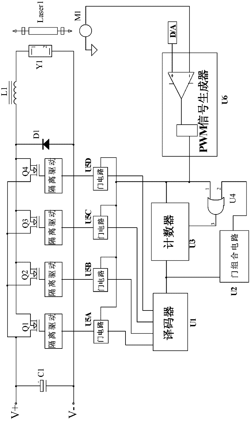
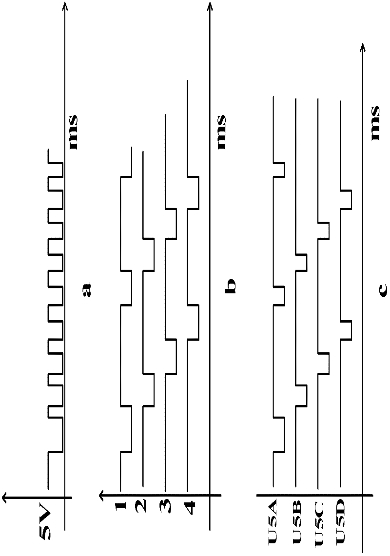
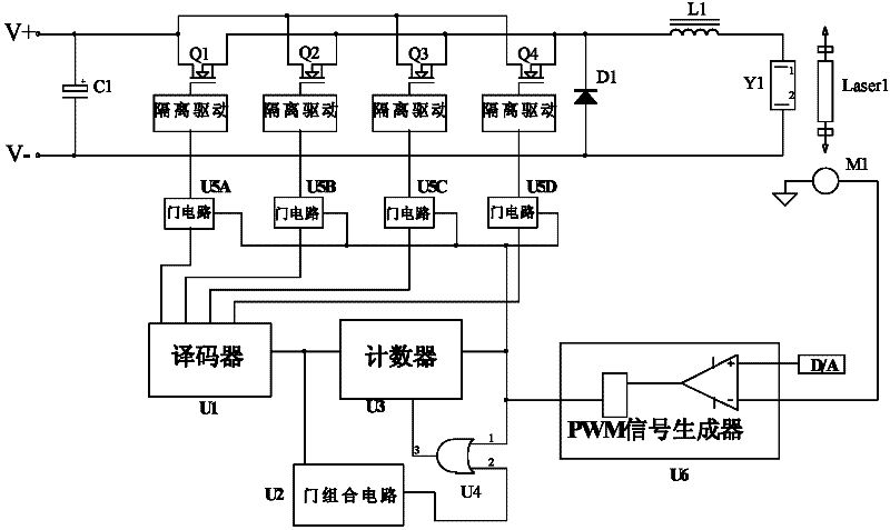
[0024] a kind of like figure 1 , 2 The shown high-power yttrium aluminum garnet crystal YAG laser power supply uses a four-frequency pulse width modulation control circuit, including a PWM signal generator U6 using a model TL494 chip. The PWM signal generator U6 is used to control a group of parallel-connected power switch tubes Q1, power switch tube Q2, power switch tube Q3, and power switch tube Q4 to provide power for high-power YAG laser discharge. The power switch tube Q1, the power switch tube Q2, the power switch tube Q3, and the power switch tube Q4 use IGBTs of the type MDI550-12A4.

[0025] There is a four-digit frequency division circuit composed of a cascaded four-bit binary counter U3 of model 74HC93 and a three-eight line decoder U1 of model 74HC138. The input end of the four-bit binary counter U3 is connected with th...


PUM


Abstract

The invention discloses a multi-frequency division pulse width modulation control circuit for a high-power laser power supply; the circuit comprises a PWM (Pulse Width Modulation) signal generator for controlling a group of in-parallel power switching tubes to provide power for high-power laser discharge, and at least three frequency division circuits composed of cascaded counters and decoders, wherein the input ends of the counters are connected with the output end of the PWM signal generator; the output ends of the decoders and the output end of the PWM signal generator are simultaneously connected with a group of in-parallel gate circuits; and each output end of the group of in-parallel gate circuits is connected with the control ends of the group of in-parallel power switching tubes respectively and correspondingly to form at least three frequency division PWM control circuits. The multi-frequency division pulse width modulation control circuit not only can reduce working frequency of single power switching tube and improve total working switching frequency of a power supply, power conversion efficiency and stability, but also can reduce temperature of radiating fins and volume of the power supply, and effectively solves the current-sharing problem among the plurality of power switching tubes. Therefore, the control circuit is applicable to the high-power laser power supply more than 12 KW.

Description

technical field [0001] The invention relates to a laser power supply, in particular to a multi-frequency division pulse width modulation control circuit for a high-power laser power supply. Background technique [0002] Most of the existing high-power laser discharge power supplies use pulse width modulation (Pulse Width Modulation, abbreviated as PWM) control circuits without frequency division or two frequency division. The former controls the operation of a single power switch tube, and the latter Control two parallel power switch tubes to work alternately. [0003] Since the power consumption of an insulated gate bipolar transistor (Insulated Gate Bipolar Transistor, IGBT for short) working as a power switch tube is basically linearly related to the working frequency, that is, the carrier frequency. The higher the operating frequency, the greater the power consumption of the IGBT, the higher the actual temperature of the device, and the more prominent the safety hazard....

Claims


Application Information

Patent Timeline
IPC IPC(8): H02M1/088
Inventor 张肽锋
Owner UNITED WINNERS LASER CO LTD
Learn More