
Joint driving unit for sintering waste heat recovery and sintering main exhaust fan

A main exhaust fan and waste heat recovery technology, applied in the direction of machine/engine, waste heat treatment, furnace components, etc., can solve the problem of large investment cost, and achieve the effect of ensuring normal production, enhancing safety margin, and improving energy recovery efficiency

Inactive Publication Date: 2012-04-11
XIAN SHAANGU POWER
View PDF4 Cites 12 Cited by
  • Summary
  • Abstract
  • Description
  • Claims
  • Application Information

AI Technical Summary

Problems solved by technology

Separate investment in workshops and separate design of control systems is required, resulting in high investment costs

Method used


Image

  • Joint driving unit for sintering waste heat recovery and sintering main exhaust fan
  • Joint driving unit for sintering waste heat recovery and sintering main exhaust fan

Examples


Embodiment 1

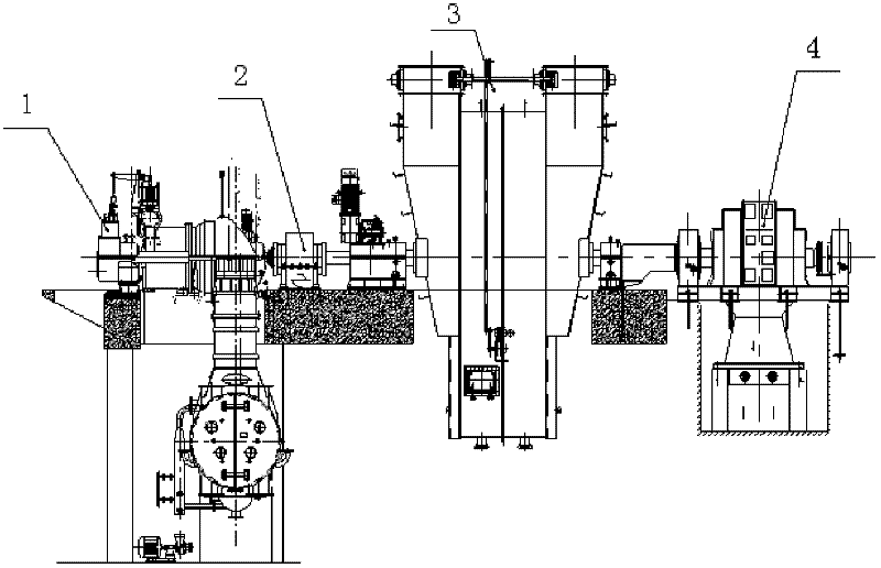
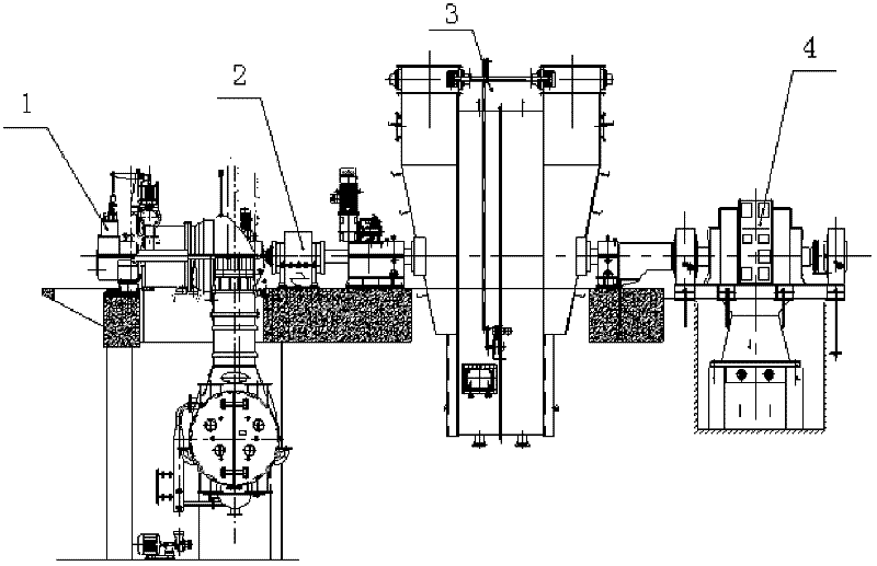
[0022] In this embodiment, the above-mentioned sintering main exhaust fan 3 with dual output shafts is specifically a centrifugal blower; the above-mentioned sintering waste heat recovery steam turbine 1 is specifically a condensing steam turbine. The condensing steam turbine 1, the centrifugal blower 3 and the synchronous motor 4 are coaxially arranged in series, wherein the centrifugal blower 3 and the condensing steam turbine 1 are coaxially connected through the variable speed clutch 2. In order to ensure the stable operation of the unit, the The automatic meshing speed of the variable speed clutch 2 is 3000r / min, that is, after the centrifugal blower 3 is started, the variable speed clutch 2 is automatically meshed when the speed of the condensing steam turbine 1 rises to 3000r / min, and the centrifugal fan with the double output shaft is driven together with the motor 4. type blower 3, the output power of the motor 4 is reduced, so as to achieve the purpose of energy savin...

Embodiment 2

[0024] In this embodiment, the rotation speed of the sintering main exhaust fan 3 is 1500r / min. According to the parameters of the waste heat steam, when the rotation speed of the waste heat steam turbine is selected to be 3000r / min, it has a higher energy recovery efficiency. The speed ratio between the sintered waste heat turbine and the sintered main exhaust fan is 2.


PUM


Abstract

The invention discloses a joint driving unit for sintering waste heat recovery and sintering main exhaust fan. The unit comprises a double-output shaft sintering main exhaust fan, a synchronous motor, a variable speed clutch and a sintering waste heat recovery steam turbine; one output shaft of the sintering main exhaust fan is coaxially connected with the synchronous motor; the other output shaft of the sintering main exhaust fan is coaxially connected with the sintering waste heat recovery steam turbine by the variable speed clutch. The unit improves the energy recovery rate of metallurgical system, which is a new energy-saving and emission-reducing device for metallurgical system.

Description

technical field [0001] The invention relates to energy recovery and utilization equipment in iron and steel metallurgical processes, in particular to a sintering waste heat recovery and sintering main exhaust fan combined drive unit. Background technique [0002] In the ironmaking process, the energy consumption of the sintering process accounts for more than 10% of the energy consumption per ton of steel, and the heat taken away by the waste gas discharged from the cooler is about 35% of the heat consumption of the sintering system. Make full use of this Part of the heat can significantly reduce the energy consumption of the sintering process, which accounts for about 12% of the total energy consumption of metallurgy, and is the second largest energy-consuming process after ironmaking. Generally, the average temperature of the sintering flue gas in the sintering plant is ≤150°C, and the temperature of the flue gas at the tail reaches 300°C to 400°C. The current waste heat ...

Claims


Application Information

Patent Timeline
IPC IPC(8): C22B1/16F27D17/00F01K27/02
CPCY02P10/25
Inventor 孙鸿声柳黎光郑秀萍牛卫民符海华李普会邓建平贾江平文省政周宁王美娜
Owner XIAN SHAANGU POWER
Learn More