Method for relieving sill-lifting cavitation of suddenly-enlarged gallery for high-lift ship locks

A high water head and ship lock technology, applied in ship locks, ship lifting devices, buildings, etc., can solve problems such as affecting the safe operation of the ship lock, airbag explosion, affecting the water filling of the ship lock, etc., so as to shorten the sudden expansion of the corridor and reduce the cavitation of the lift. , Improve the effect of engineering safety

Inactive Publication Date: 2012-04-11
NANJING HYDRAULIC RES INST
View PDF1 Cites 12 Cited by
  • Summary
  • Abstract
  • Description
  • Claims
  • Application Information

AI Technical Summary

Problems solved by technology

For example, if the gas concentration at the bottom of the cavitation zone reaches the corrosion-reducing concentration by increasing the air flow at the sill 1, the air flow at the sill 1 is very large, and the bubbles will flow out after they escape the water surface downstream. The airbags in the corridor vibrate back and forth, and even the airbags explode under suitable conditions, which will not only affect the water filling of the lock, but more importantly, affect the safe operation of the lock
[0015] To sum up, the downward-sudden-expanding corridor is a commonly used body type for high-head ship lock water delivery valves, but the cavitation problem of this body type needs to be solved urgently

Method used


Image

  • Method for relieving sill-lifting cavitation of suddenly-enlarged gallery for high-lift ship locks
  • Method for relieving sill-lifting cavitation of suddenly-enlarged gallery for high-lift ship locks
  • Method for relieving sill-lifting cavitation of suddenly-enlarged gallery for high-lift ship locks

Examples


Embodiment 1

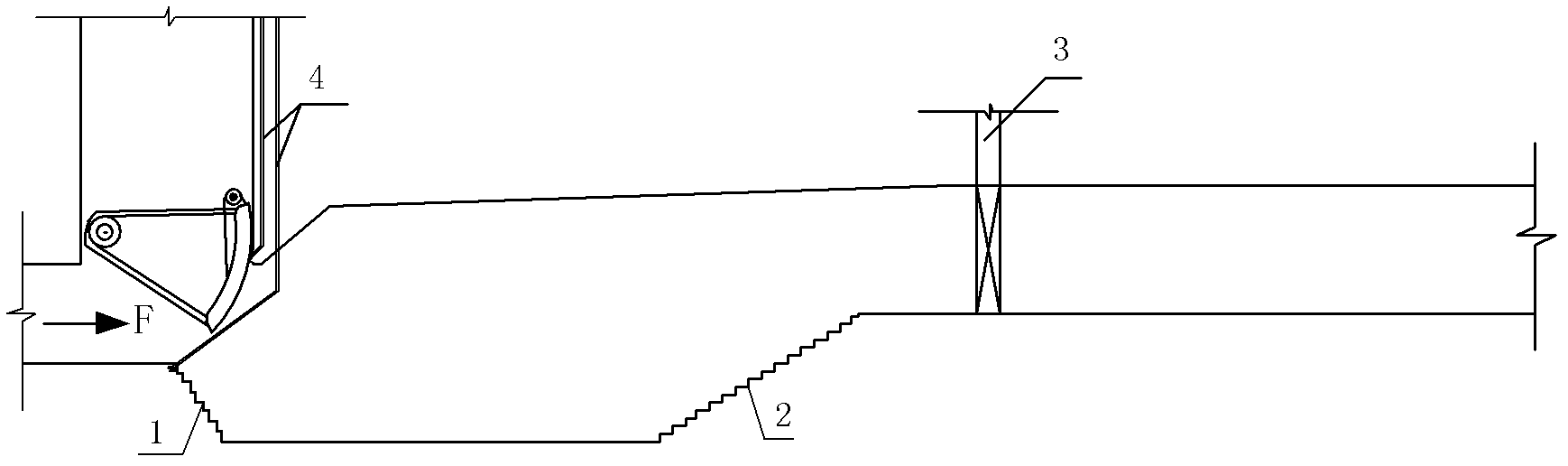
[0034] This embodiment is a method for reducing the cavitation of the sudden expansion corridor of the high water head ship lock. Figure 4 It is the shape figure of the ship lock water delivery valve of the present embodiment, Figure 5 It is a large sample diagram of the rising sill aeration facility of this embodiment. Such as Figure 4 As shown, the rising sill 2 adopts a quintic curve-type sill, and the sill aeration facility 5 (in the form of a sill + aeration tank) is installed at the position where the water flow separates on the curved surface of the sill to form a stable low-pressure area. 4 is arranged on both sides of the aeration facility 5 of the ascending ridge, and aerates into the water flow. The ventilation pipe 4 leads to the top of the gate, and the way of ventilating into the water flow depends on the pressure in the aeration tank 5, such as the negative pressure in the aeration tank can suck enough air to make the cavitation zone of the cavitation zone ...

Embodiment 2

[0039] Figure 8 is the second embodiment of the present invention, Figure 9 It is a large sample diagram of the rising sill aeration facility of this embodiment. The ramp-up curve of this embodiment is the same as that of Embodiment 1, and a quintic curve is also used, the difference is that the ramp-up aeration facility is an aeration tank type. The sill 2 adopts a quintic curve-type sill, and the sill aeration facility 5 (in the form of an aeration tank) is installed at the position where the water flow separates on the curved surface of the sill to form a stable low-pressure area. The both sides of air facility 5, aerate in the water flow. The ventilation pipe 4 leads to the top of the gate, and the way of ventilating into the water flow depends on the pressure in the aeration tank 5, such as the negative pressure in the aeration tank can suck enough air to make the cavitation zone of the cavitation zone and the downstream aeration tank 3. When the aeration concentrati...

Embodiment 3

[0041] Figure 10 is the third embodiment of the present invention, Figure 11 It is a large sample diagram of the rising sill aeration facility of this embodiment. In this embodiment, both the falling slope and the rising slope curve adopt a step type, and the rising slope aeration facilities are in the form of aeration tanks. The sill 2 adopts a stepped sill, and the sill aeration facility 5 (aeration tank type) is installed at the position where the water flow is separated on the curved surface of the sill to form a stable low-pressure area. The ventilation pipe 4 is arranged on the aeration facility of the sill The two sides of 5, aerate in the water flow. The ventilation pipe 4 leads to the top of the gate, and the way of ventilating into the water flow depends on the pressure in the aeration tank 5, such as the negative pressure in the aeration tank can suck enough air to make the cavitation zone of the cavitation zone and the downstream aeration tank 3. When the aera...


PUM


Abstract

The invention relates to a method for relieving the body-type cavitation of a suddenly-enlarged gallery for ship locks and particularly relates to a method for relieving the sill-lifting cavitation of a suddenly-enlarged gallery for high-lift ship locks. The method is characterized in that a position to which a flow separation occurs on a sill-lifting curved surface is provided with a sill-lifting aeration device, the sill-lifting aeration device is an aerating groove or is formed by connecting an aerating sill with an aerating groove, the inside of the aerating groove is provided with a ventilating pipe communicated with the top of a lock, the top of the ventilating pipe is also connected to an air compressor by connecting a branch pipe, and the branch pipe is provided with a valve; and when the negative pressure exerted on the rear low-pressure area of the sill-lifting aeration device is large enough to automatically suck air into water, the ventilating pipe is communicated with the atmosphere so as to realize natural ventilation, otherwise, air is added into the sill-lifting aeration device by using the air compressor so as to achieve the purpose of relieving the downstream sill-lifting and gate-slot cavitation of the sill-lifting aeration device.

Description

technical field [0001] The invention relates to a method for reducing cavitation in the sudden expansion corridor of a ship lock, in particular to a method for reducing cavitation in the sudden expansion corridor of a high water head ship lock. Background technique [0002] With the development of the shipping industry and the improvement of the valve research level, the ship lock is entering a period of high water head, and "high water head and large flow" are the main characteristics of the current ship lock. At present, there are more than 50 ship locks with a water head exceeding 20m that have been built or are under construction in my country. Among them, the water head of Caojie Ship Lock is 26.7m, the water head of Yinpan is as high as 36.46m, and the maximum water head of Three Gorges Ship Lock is as high as 45.2m. [0003] As far as the ship lock is concerned, the water delivery valve is its control device, and the cavitation of its valve section has always been th...

Claims


Application Information

Patent Timeline
Patent Type & Authority Applications(China)
IPC IPC(8): E02C1/08
Inventor 胡亚安凌国增严秀俊刘本芹阮士平李中华
Owner NANJING HYDRAULIC RES INST
Why Eureka
Try Eureka