Synchronous control device of revolving speed of hydraulic walking mechanism engine and discharge of main pump

A technology of engine speed and synchronous control, which is applied in the direction of fluid pressure actuators, mechanical equipment, servo motors, etc., can solve problems such as the inability to realize synchronous and coordinated control of engine speed, achieve fuel consumption savings, reduce operating procedures, and avoid stalling Effect

Inactive Publication Date: 2012-04-11
徐州雷曼机械科技有限公司 +1
View PDF6 Cites 14 Cited by
  • Summary
  • Abstract
  • Description
  • Claims
  • Application Information

AI Technical Summary

Problems solved by technology

The speed of the engine is basically constant. When changing the speed of the engine, it is necessary to manually adjust the size of the throttle. It is impossible to realize the synchronous and coordinated control of the engine speed and the displacement of the variable hydraulic pump.

Method used


Image

  • Synchronous control device of revolving speed of hydraulic walking mechanism engine and discharge of main pump
  • Synchronous control device of revolving speed of hydraulic walking mechanism engine and discharge of main pump
  • Synchronous control device of revolving speed of hydraulic walking mechanism engine and discharge of main pump

Examples


Embodiment Construction

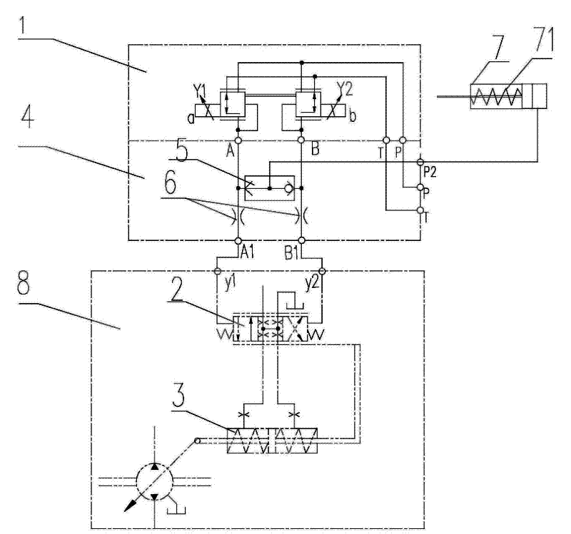
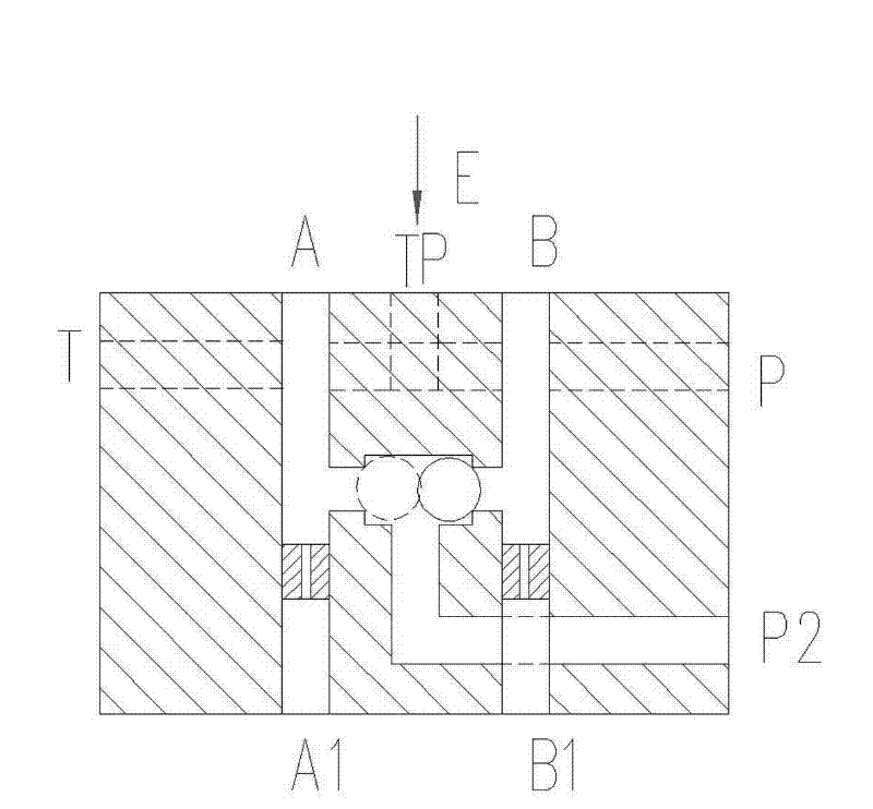
[0012] like figure 1 As shown in the figure, the main pump 8 is the power component of the driving locomotive in the system, and it has two external control ports y1, y2, which are the control ports of the variable servo valve 2 of the main pump; the proportional pressure reducing valve 1 It is a standard hydraulic component, which adopts explosion-proof proportional decompression (DHRZA / M-A-012) imported from Italy. It has 4 oil ports, P T A B. The P port of proportional decompression valve 1 is connected to the pilot pressure oil inlet port, and the oil return port T Oil tank; port A and port B are the output ports of the proportional pressure reducing valve, which reflect the magnitude of the input electrical signal, and are respectively connected to the control ports y1 and y2 of the variable servo valve 2 of the main pump. The change of y1 and y2 makes the valve output a differential pressure signal to control the pump variable Piston 3 realizes the variable control of th...


PUM


Abstract

The invention discloses a synchronous control device of revolving speed of a hydraulic walking mechanism engine and discharge of a main pump, belonging to the filed of mine and engineering machinery. The synchronous control device comprises a proportional pressure reducing valve, a main pump servo valve and an accelerator control cylinder, wherein a valve block is arranged between the proportional pressure reducing valve and the main pump servo valve; a shuttle valve and two throttle plugs are embedded into the pressure reducing valve. Two ends of the shuttle valve are respectively connected between an output port A and an output port B of the proportional pressure reducing valve. The proportional pressure reducing valve controls the servo valve of a variable pump through a throttle plug hole; an output pressure signal of the proportional pressure reducing valve at the left side or the right side is output to the accelerator control cylinder through the output port of the shuttle valve to control the stroke of an oil cylinder so as to control an accelerator of the engine. The synchronous control device disclosed by the invention has the advantages that a motor car can be operated to move forwards or backwards or to change speed by operating a discharge handle of the pump only; the revolving speed of the engine is automatically adjusted to match with the power requirement of the pump while the variable of the pump is controlled, and therefore the problem that the engine is suffocated and switched off due to mismatching between the discharge of the pump and the accelerator of the engine during starting the motor car can be prevented.

Description

technical field [0001] The invention belongs to the fields of mining machinery and engineering machinery, and in particular relates to a synchronous control device for engine speed and main pump displacement of hydraulic traveling machinery, which is mainly applicable to the control of mining hydraulic monorail locomotives and engineering machinery engines. Background technique [0002] The driving of mining hydraulic monorail locomotives is often controlled by a closed system oil pump driving a low-speed, high-torque hydraulic motor. Its driving speed and forward, reverse or stop depend on the change of the displacement of the main oil pump and the conversion of the flow output and input ports. . The speed of the engine is basically constant. When changing the speed of the engine, it is necessary to manually adjust the size of the throttle, which cannot realize the synchronous and coordinated control of the speed of the engine and the displacement of the variable hydraulic ...

Claims


Application Information

Patent Timeline
Patent Type & Authority Applications(China)
IPC IPC(8): F15B11/02F15B11/04
Inventor 刘学典殷宪阁秦昌永李宾金第徐伟
Owner 徐州雷曼机械科技有限公司
Why Eureka
Try Eureka