Composite phase change heat exchanger for flue gas heat recovery of boiler

A composite phase-change heat and waste heat recovery technology, which is applied to feed water heaters, preheating, lighting and heating equipment, etc., can solve the problems of difficult layout of tubular phase-change heat exchangers, eliminate the risk of low-temperature corrosion, reduce The effect of dust accumulation and convenient arrangement

Inactive Publication Date: 2012-04-11
王海波
View PDF17 Cites 15 Cited by
  • Summary
  • Abstract
  • Description
  • Claims
  • Application Information

AI Technical Summary

Problems solved by technology

[0006] The purpose of the present invention is to solve the problems existing in the above-mentioned prior art, solve the problem of difficult arrangement of vertical flue or inclined flue pipe type phase change heat exchanger, and realize efficient recovery of flue gas waste heat

Method used


Image

  • Composite phase change heat exchanger for flue gas heat recovery of boiler
  • Composite phase change heat exchanger for flue gas heat recovery of boiler
  • Composite phase change heat exchanger for flue gas heat recovery of boiler

Examples


Embodiment 1

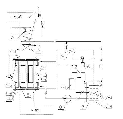
[0044] Composite phase change heat exchanger for waste heat recovery of boiler flue gas (see attached figure 1 and accompanying drawings), use air 13 and cold fluid 11 such as low-temperature water (or heat transfer oil) as working fluids for recycling waste heat, including boiler flue 1, internal and external equipment in the flue, and connecting pipes, control instrument valves . The flue 1 is equipped with a fluid heater 10, a composite phase change heat exchanger 4, the original economizer 2 of the boiler, an air preheater 3, and the dust removal and desulfurization equipment of the original boiler. Outside the flue, there are thermostat 7, heat exchanger 9, frequency modulation water pump 8 and its supporting pipes, instrument valves and so on.

[0045] The composite phase change heat exchanger 4 mainly includes an inner heat exchange tube 4-1, a casing 4-2, a first tube sheet 4-3, a second tube sheet 4-4 and a box 4 between the tube sheets -5. Among them, the air goe...

Embodiment 2

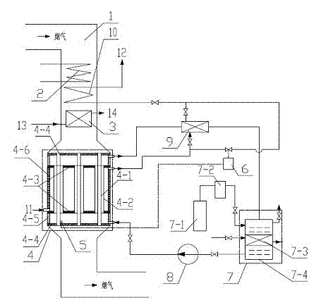
[0050] Composite phase change heat exchanger for waste heat recovery of boiler flue gas (see attached figure 2 and accompanying drawings), using cold fluid 11 such as low-temperature water (or heat transfer oil) as a working medium for recycling waste heat, including boiler flue 1, internal and external equipment of the flue, connecting pipes, and control instrument valves. The flue 1 is equipped with a fluid heater 10, a composite phase change heat exchanger 4, the original economizer 2 of the boiler, an air preheater 3, and the dust removal and desulfurization equipment of the original boiler. Outside the flue, there are thermostat 7, heat exchanger 9, frequency modulation water pump 8 and its supporting pipes, instrument valves and so on.

[0051] The composite phase change heat exchanger 4 mainly includes an inner heat exchange tube 4-1, a casing 4-2, a first tube sheet 4-3, a second tube sheet 4-4 and a box 4 between the tube sheets -5 and 4-6. Among them, the cold flu...

Embodiment 3

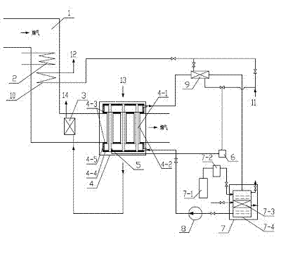
[0057] The composite phase change heat exchanger 4 of the present invention can also be arranged in a horizontal flue, such as image 3 shown. The flue gas passes through the shell side outside the casing, and the cold fluid to be heated passes through the tube side of the inner heat exchange tube. The specific implementation method is the same as above.


PUM


Abstract

The invention discloses a composite phase change heat exchanger for flue gas heat recovery of boiler, comprising an original coal saving device and an air pre-heater of the boiler, a fluid heater disposed in the flue, a composite phase change heat exchanger, and a temperature adjustor disposed outside the flue, a heat exchanger, a frequency modulation water pump, a pipeline and an instrument valve which are matched; the composite phase change heat exchanger is a three-process integrated structure composed of an inner heat exchange pipe process, a sleeve pipe process between the inner heat exchange pipe process and the sleeve pipe and a shell process outside the sleeve pipe. The composite phase change heat exchanger of the invention has a compact structure, which can be conveniently disposed in a vertical, horizontal or oblique flue; simultaneously, the adjustment is flexible, which can effectively avoid low-temperature corrosion, so that the boiler can be operated economically, safely and efficiently. Compared to the technology of the composite phase change heat exchanger developed by Mr. Yang Benluo, the composite phase change heat exchanger of the invention equals to the second-generation technology of the composite phase change heat exchanger.

Description

technical field [0001] The invention relates to a composite phase change heat exchanger used for boiler flue gas waste heat recovery, which belongs to the field of boiler flue gas waste heat recovery. Background technique [0002] An economizer and / or an air preheater are usually installed in the tail flue of the boiler to absorb part of the waste heat of the flue gas, but the exhaust gas temperature is usually 140°C to 160°C or higher. Due to the existence of sulfide in the flue gas, the outlet temperature of the flue gas on the heating surface at the tail of the air preheater is limited. If the exhaust gas temperature is too low, the temperature of the wall surface on the heating surface will be lower than the acid dew point of the flue gas, resulting in serious condensation corrosion, Ash plugging or even perforation is a difficult problem that must be overcome to continue to utilize the waste heat of the flue gas and reduce the temperature of the exhaust gas. [0003] P...

Claims


Application Information

Patent Timeline
Patent Type & Authority Applications(China)
IPC IPC(8): F22D1/38F23L15/00
CPCY02E20/34
Inventor 王海波董立军王海军
Owner 王海波
Why Eureka
Try Eureka