
Optical electric field sensor

An optical electric field and sensor technology, applied in the direction of electrostatic field measurement, instruments, and measurement of electrical variables, can solve the problems that the stability cannot be effectively solved, and the stability of the sensor is easily affected by factors such as ambient temperature and vibration, etc. The effect of mass production and simplified manufacturing process

Inactive Publication Date: 2012-04-11
HUAZHONG UNIV OF SCI & TECH
View PDF5 Cites 8 Cited by
  • Summary
  • Abstract
  • Description
  • Claims
  • Application Information

AI Technical Summary

Problems solved by technology

[0003] The optical electric field sensor based on the principle of linear electro-optic effect has been used to measure the electric field distribution and the high voltage of the power system bus, but the stability of the sensor is easily affected by factors such as ambient temperature and vibration. A typical solution to improve its stability is The reflective double optical path structure is adopted. In the scheme, the linear electro-optic effect of an optical crystal is used to sense the measured electric field. When the interference birefringence caused by factors such as temperature and vibration is much smaller than the birefringence caused by the electric field, two optical paths are used. The output is calculated to deal with the influence of interference factors, but according to the actual measurement and operation results, its long-term operation stability has not been effectively solved

Method used


Image

  • Optical electric field sensor
  • Optical electric field sensor
  • Optical electric field sensor

Examples


Embodiment Construction

[0017] The present invention will be described in more detail below with the help of examples, but the following examples are only illustrative, and the protection scope of the present invention is not limited by these examples.

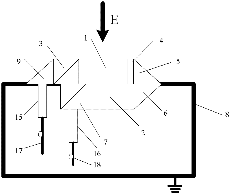
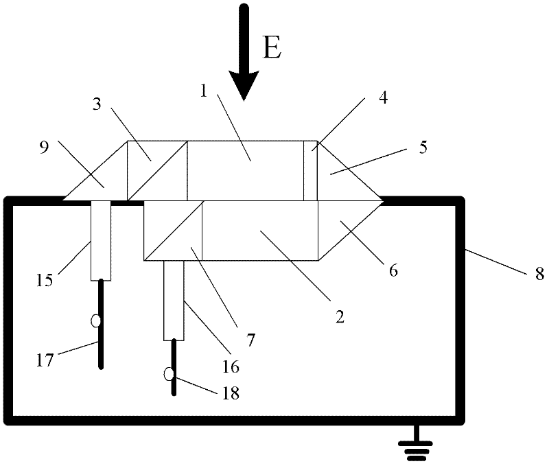
[0018] Such as figure 1 As shown, a kind of passive optical electric field sensor provided by the present invention comprises incident optical fiber 17, fiber collimator 15, triangular prism 9, incident light polarizer 3, first optical crystal 1, half-wave plate 4, triangular prism 5 , triangular prism 6, second optical crystal 2, analyzer 7, fiber collimator 16, exit fiber 18 and ground electrode 8.

[0019] The first optical crystal 1 is in the measured electric field E, the second optical crystal 2 is in the ground electrode 8 , and the electric field strength of the environment where the second optical crystal 2 is located is zero.

[0020] The optical path between the first optical crystal 1 and the second optical crystal 2 passes through the h...


PUM


Abstract

The invention discloses a passive optical electric field sensor for measuring electric fields or high voltages, belonging to the technical field of electric measurement. The passive optical electric field sensor comprises two optical crystals, wherein one of the optical crystals is positioned in the environments of a tested electric field as well as interference fields such as temperature, vibration and the like, and the other optical crystal is only positioned in the environments of interference fields such as the same temperature, vibration and the like; and after polarized light is emittedby the two crystals, modulation of interference fields such as temperature, vibration and the like is eliminated. A signal which is proportional to the tested electric field or a high voltage is output though a signal processing circuit, and is not influenced by interference factors such as temperature, vibration and the like. The optical electric field sensor disclosed by the invention can be used for measuring electric fields or high voltages, is particularly used for detecting electric fields in the power industry, monitoring electric fields or high voltages of buses, has high stability, and is not influenced by temperature or stress easily.

Description

technical field [0001] The invention belongs to the technical field of electrical measurement, and in particular relates to a passive optical electric field sensor for measuring electric field or voltage. The electric field sensor has high stability and wider bandwidth than traditional sensors. Background technique [0002] Electric field measurement is of great significance in many fields of scientific research and engineering technology, especially in the fields of power system, electromagnetic compatibility and microwave technology. For example, in the power industry, electric field measurement can be used for power system status monitoring, electric field distribution measurement inside and outside electrical equipment, high voltage test and corona discharge phenomenon research, power system bus high voltage measurement, etc.; in the field of electromagnetic compatibility research, electric field measurement It can be used to detect external electromagnetic radiation an...

Claims


Application Information

Patent Timeline
IPC IPC(8): G01R19/00G01R29/14G01R15/24
Inventor 肖霞徐雁徐垦
Owner HUAZHONG UNIV OF SCI & TECH
Learn More