Multifrequency probe light time division multiplexing coherent light time domain reflectometer method and apparatus thereof

A technology of time domain reflectometer and time division multiplexing, which is applied in electromagnetic wave transmission system, electrical components, transmission system, etc., can solve problems such as influence, and achieve the effect of improving measurement speed

Inactive Publication Date: 2012-04-11
NANJING UNIV
View PDF2 Cites 31 Cited by
  • Summary
  • Abstract
  • Description
  • Claims
  • Application Information

AI Technical Summary

Problems solved by technology

However, this method can only detect one frequency at a time, and the control of the laser requires additional circuit design. The control accuracy is greatly affected by the control circuit hardware and

Method used


Image

  • Multifrequency probe light time division multiplexing coherent light time domain reflectometer method and apparatus thereof
  • Multifrequency probe light time division multiplexing coherent light time domain reflectometer method and apparatus thereof
  • Multifrequency probe light time division multiplexing coherent light time domain reflectometer method and apparatus thereof

Examples


Embodiment 1

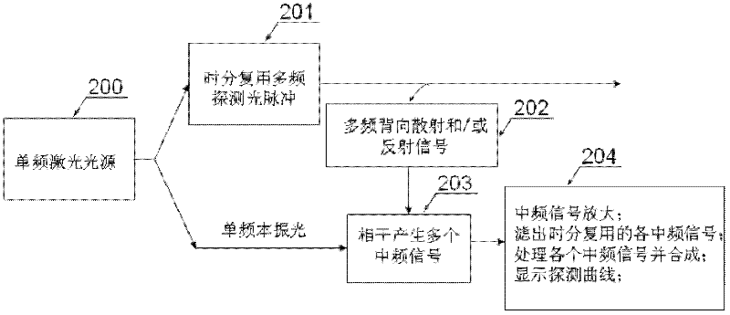
[0038] See figure 1 , a method for multi-frequency detection optical time division multiplexing coherent optical time domain reflectometer provided by the embodiment of the present invention, the detailed content of the method is as follows:

[0039] 200: The laser light emitted by the single-frequency laser source is divided into two paths by the beam splitter, one path is modulated by the phase modulator to generate multi-frequency light, and the other path is used as single-frequency local oscillator light;

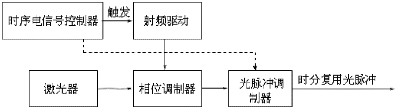
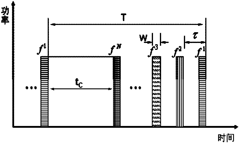
[0040] 201: The modulation depth of the phase modulator is greater than 1, and the phase modulator and the optical pulse modulator are synchronously controlled by a time-sequence electrical signal to generate a time-division multiplexing detection optical pulse; the control process of the time-sequence electrical signal is as follows figure 2 As shown, the RF drive of the phase modulator generates frequency pulses with a time sequence structure under the trigger of a ...

Embodiment 2

[0045] See Figure 5 , the embodiment of the present invention provides a method and device for a multi-frequency detection optical coherent optical time domain reflectometer. The details of the method and device are as follows:

[0046] The light emitted by the single-frequency laser light source 1 is divided into two beams by the 90:10 beam splitter 2, and one end of the high-power output is connected to the probe light path, and the driving voltage of the phase modulator 3 is set so that the modulation depth is 2.405. The power of the 0-order frequency in the power spectrum of the multi-frequency light output by the modulator 3 is the lowest, and most of the power is concentrated on the ±1-order and ±2-order frequencies, and its power spectrum structure is as follows Figure 4 shown;

[0047] The multi-frequency detection light output by the phase modulator 3 is then amplified by an optical amplifier 4, such as an erbium-doped fiber amplifier to increase the power of the d...

Embodiment 3

[0061] See Figure 12 , another multi-frequency detection optical coherent optical time domain reflectometer device provided by the embodiment of the present invention, the device is basically the same in structure as the embodiment 2, except that the optical pulse modulator in the system uses an acousto-optic modulator 18 . Since the acousto-optic modulator 18 has a frequency-shifting effect, an acousto-optic modulator 18 with the same frequency-shifting characteristics is also used in the local oscillator optical path of the coherent detection module, but it works in continuous optical mode only for frequency-shifting, Therefore, the zero-order frequency in the multi-frequency probe light pulse is the same as the frequency of the local oscillator light. This ensures that coherent IF signals appear as Image 6 The results shown.


PUM


Abstract

The invention provides a method of a multifrequency probe light time division multiplexing coherent light time domain reflectometer. The method is characterized in that: a detection light pulse being injected into a fiber being detected is multifrequency detection light pulse which generates time division multiplexing by utilizing sequential electric signal synchronization control phase modulator and light pulse modulator modulation; local oscillator light is single-frequency light, and power spectrum of the multifrequency detection light pulse is bilaterally symmetrical relative to local oscillator light frequency; 0 order frequency of the multifrequency detection light pulse is same with the local oscillator light frequency; modulation depth of the phase modulator is larger than 1; a backward scattering and/or reflection signal which the multifrequency light pulse of time division multiplexing is in mixes with the local oscillator light in a coherent detection module, both side are coherent and an intermediate frequency signal of time division multiplexing is output by a photoelectric detector; an intermediate frequency signal processing module amplifies an intermediate frequency signal of time division multiplexing detected by coherent detection, according to a characteristic of the intermediate frequency signal, a needed band pass filter is selected, the intermediate frequency signal is filtered, a subsequent circuit carries out real-time processing on a plurality of paths of intermediate frequency signals, and information of the fiber being detected is displayed.

Description

Technical field: [0001] The invention relates to a coherent optical time domain reflectometer used for characterization and fault location of optical fibers in optical communication lines, especially for long-distance, multi-relay amplified submarine communication optical cable health monitoring. Background technique: [0002] At present, commercial coherent optical time domain reflectometry (COTDR) instruments use single-frequency narrow-linewidth detection optical pulses, and the electrical signal generated by coherent detection is only a single intermediate frequency signal. By detecting the power of the intermediate frequency signal over time, the optical fiber The health of the line. Under certain pulse width conditions, the dynamic range can be improved by increasing the pulse peak power or increasing the average number of data, but the peak power is limited by the nonlinear effect of the fiber. Since the photoelectric signal processing module of the commercial system...

Claims


Application Information

Patent Timeline
IPC IPC(8): H04B10/08H04B10/071
Inventor 张旭苹吕立冬宋跃江
Owner NANJING UNIV
Why Eureka
Try Eureka