Linear cutting molybdenum wire tensile force automatic control system and tensile force control method

An automatic control system and tension force technology, applied in electrode manufacturing, manufacturing tools, electric machining equipment, etc., can solve the problems of affecting machining accuracy, machining instability, roughness increase, etc., and reduce the breakage rate of molybdenum wire. , Improve the surface finish, improve the effect of the tightness of the molybdenum wire

Inactive Publication Date: 2012-04-18
NINGBO HUIJIN METAL PRODS
View PDF7 Cites 12 Cited by
  • Summary
  • Abstract
  • Description
  • Claims
  • Application Information

AI Technical Summary

Problems solved by technology

If the tension of the molybdenum wire is not adjusted in time, the loose molybdenum wire will not get the ideal cutting effect, which will lead to unstable processing, which will affect the processing quality and production efficiency in the slightest, and cause broken wires in severe cases.
[0003] Therefore, a molybdenum wire tensioning device is needed to adjust the tension of the molybdenum wire. At present, the molybdenum wire tensioning device of the wire cutting machine tool is a single mechanical structure, and the tension of the molybdenum wire is generally controlled by adjusting the spring. Tension force, in actual processing, the aging of the spring sheet will change the elastic modulus coefficient, the tension force cannot be kept constant when the molybdenum wire is running, and the wire running jitter cannot be automatically stabilized in a quantifiable range
Increase the surface roughness of the machined parts and cause streaks, which greatly affect the machining accuracy
Affect the service life of molybdenum wire

Method used


Image

  • Linear cutting molybdenum wire tensile force automatic control system and tensile force control method
  • Linear cutting molybdenum wire tensile force automatic control system and tensile force control method
  • Linear cutting molybdenum wire tensile force automatic control system and tensile force control method

Examples


Embodiment Construction

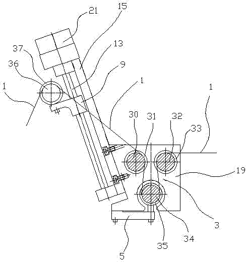
[0016] The present invention will be described in further detail below in conjunction with accompanying drawing and specific embodiment: see Figure 1~5 , a wire-cut molybdenum wire tension automatic control system, including a mounting plate 3, the mounting plate 3 is provided with a first guide wheel cover 31, a second guide wheel cover 33 and a third guide wheel cover 35, wherein the first A guide wheel cover 31 is provided with a first guide wheel 30, a second guide wheel cover 33 is provided with a second guide wheel 32, and a third guide wheel cover 35 is provided with a third guide wheel 34, specifically see figure 1 , Figure 5 .

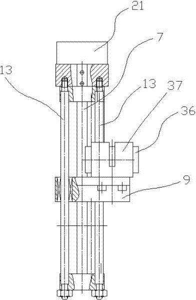
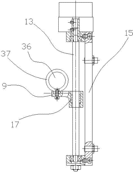
[0017] The side of the mounting plate 3 is connected with a bottom plate 15 by bolts, and a stepping motor 21 is arranged on the upper end of the bottom plate 15 . The stepper motor 21 is connected to a single-chip microcomputer. (The single-chip microcomputer is not shown in the figure), of course, the single-chip microcomputer can also ...


PUM


Abstract

The invention discloses a linear cutting molybdenum wire tensile force automatic control system and tensile force control method. The linear cutting molybdenum wire tensile force automatic control system comprises a plurality of guide wheels, a driving device, a sensor and a control unit, wherein molybdenum wire are wound on the guide wheels; the driving device is used for driving one guide wheel to slide; and the control unit receives a sensor signal and allows the driving device to drive the guide wheels to slide. The tensile force control method comprises the following steps: presetting a standard value on a singlechip; allowing the senor to acquire the value of the ensile force of a molybdenum wire; allowing the singlechip to convert the value of the tensile force into a comparison value; summing the comparison value and a standard value to obtain a driving value; if the driving value is bigger than zero, allowing a step motor to rotate anticlockwise, and if the driving value is smaller than zero, allowing the step motor to rotate clockwise; and repeating the previous step till the driving value is zero. In the invention, the tensile force of the molybdenum wire can be regulated automatically, and the smooth finish of a machined part can be improved greatly.

Description

technical field [0001] The invention relates to an automatic control system for tension force of wire cutting molybdenum wire. Background technique [0002] During the use of wire cutting, the molybdenum wire will undergo thermal elongation and discharge loss, so after a period of use, the diameter of the molybdenum wire becomes thinner and the tension of the molybdenum wire decreases. If the tension of the molybdenum wire is not adjusted in time, the loose molybdenum wire will not get the ideal cutting effect, which will lead to unstable processing, which will affect the processing quality and production efficiency in the slightest, and cause broken wires in severe cases. [0003] Therefore, a molybdenum wire tensioning device is needed to adjust the tension of the molybdenum wire. At present, the molybdenum wire tensioning device of the wire cutting machine tool is a single mechanical structure, and the tension of the molybdenum wire is generally controlled by adjusting th...

Claims


Application Information

Patent Timeline
Patent Type & Authority Applications(China)
IPC IPC(8): B23H7/10
Inventor 王成
Owner NINGBO HUIJIN METAL PRODS
Why Eureka
Try Eureka