Hartmann wavefront sensor based on diffraction grating arrays

A diffraction grating and sensor technology, applied in the field of optical detection, achieves the effect of stable performance and simple structure

Inactive Publication Date: 2012-04-18
SICHUAN UNIV
View PDF4 Cites 28 Cited by
  • Summary
  • Abstract
  • Description
  • Claims
  • Application Information

AI Technical Summary

Problems solved by technology

[0005] The purpose of the present invention is to overcome the contradiction between the measurement dynamic range and measurement accuracy in the existing Hartmann wavefront sensor, and to provide a simple structure, strong application and adaptability, based on the diffraction grating array Hartmann wavefront sensor with adjustable measurement dynamic range while maintaining high measurement accuracy

Method used


Image

  • Hartmann wavefront sensor based on diffraction grating arrays
  • Hartmann wavefront sensor based on diffraction grating arrays
  • Hartmann wavefront sensor based on diffraction grating arrays

Examples


Embodiment 1

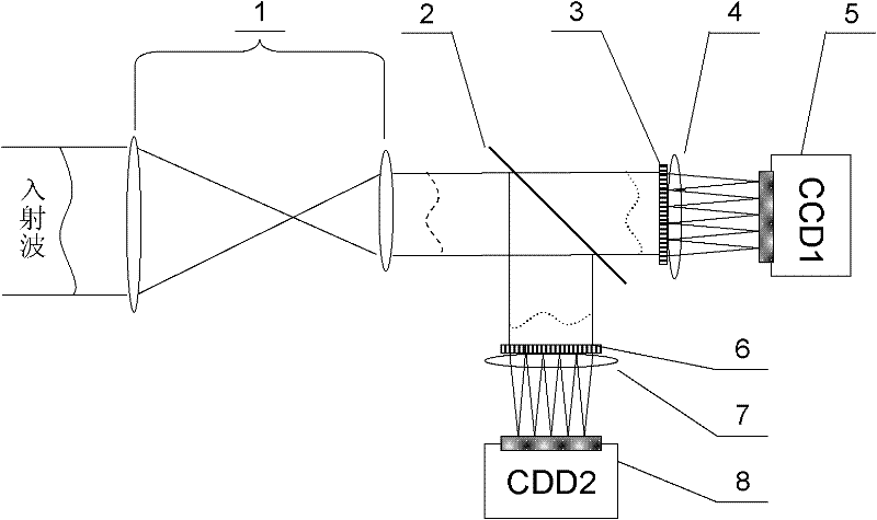
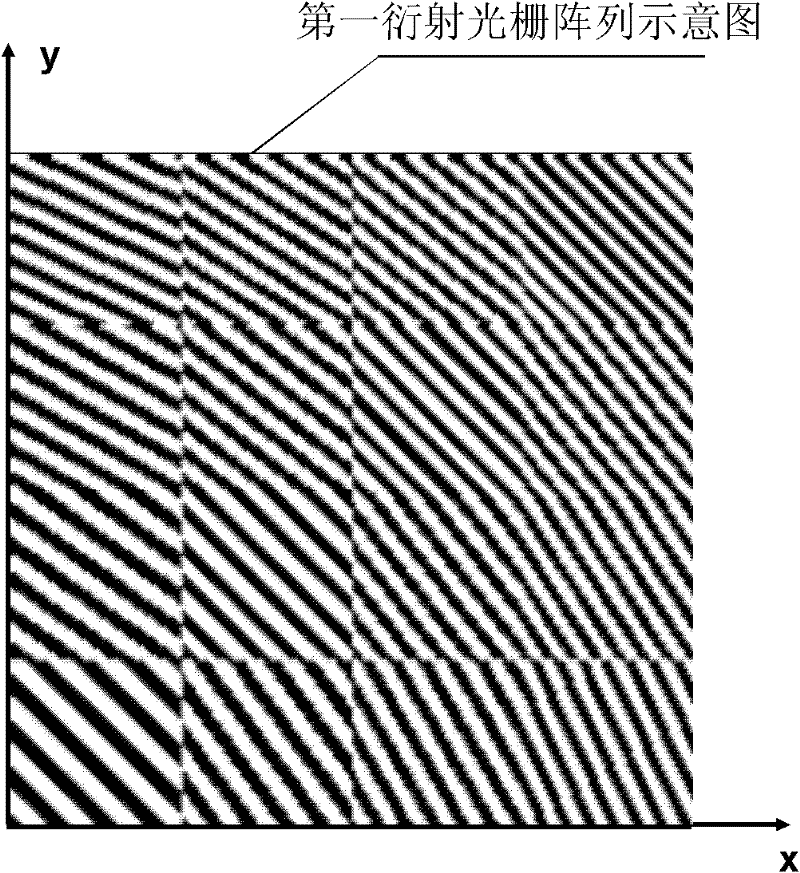
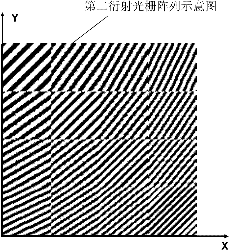
[0033] In this example, the variable spatial frequency sub-grating structure of the first diffraction grating array 3 and the second diffraction grating array 6 adopts a liquid crystal spatial light modulator with electrical addressing pure phase modulation, and the optical matching system 1 adopts a magnification factor of 5 In the telescope system, the beam splitter 2 uses a plate beam splitter with a transmittance ratio of 5:5. In order to eliminate the additional wavefront distortion introduced by the Fourier lens, the first Fourier lens 4 and the second Fourier lens 7 both use an aberration-ablation lens with a focal length of 100 mm. , CCD1 detector 5 and CCD2 detector 8 are both MVC-II1M area array CCD photodetectors with a pixel size of 1024×1280.

[0034] Such as figure 1 As shown, the Hartmann wavefront sensor based on the diffraction grating array of the present invention includes an optical matching system 1 and a beam splitter 2 behind it, and the transmission sur...

Embodiment 2

[0051] In this example, the variable spatial frequency sub-grating structure of the first diffraction grating array 3 and the second diffraction grating array 6 adopts a liquid crystal spatial light modulator with electrical addressing amplitude modulation, and the optical matching system 1 adopts a multiplier of 5. The adjusted telescope system, the beam splitter 2 adopts a beam splitting prism with a splitting ratio of 5:5, in order to eliminate the additional wavefront distortion introduced by the Fourier lens, the first Fourier lens 4 and the second Fourier lens 7 both use aberration aberration with a focal length of 100mm The lens, CCD1 detector 5 and CCD2 detector 8 all adopt the area array CCD photodetector of model MVC-II1M with a pixel size of 1024×1280.

[0052] Such as Image 6 As shown, the present invention is based on the Hartmann wavefront sensor of the diffraction grating array, including the optical matching system 1 and the beam splitter 2 behind it, and the ...


PUM


Abstract

The invention relates to a Hartmann wavefront sensor based on diffraction grating arrays. The sensor comprises an optical matching system, a first Fourier lens, a second Fourier lens, a charge coupled device (CCD) 1 detector, a CCD 2 detector, a spectroscope, a first diffraction grating array and a second diffraction grating array, wherein both the first diffraction grating array and the second diffraction grating array are formed by tightly arranging sub gratings with variable spatial frequency; the first diffraction grating array and the second diffraction grating array are respectively coupled with the first Fourier lens and the second Fourier lens which are attached to the front face or the back face to realize wavefront aperture cutting. The am of adjusting the measurement dynamic range of the Hartmann wavefront sensor under a high precision condition is fulfilled by selecting the diffraction series of a sub grating to control the dynamic range of each sub wavefront aperture focusing facula in the CCD detectors. The problem of irreconcilable conflict between measurement precision and dynamic range of the traditional Hartmann is solved through the Hartmann wavefront sensor; and the Hartmann wavefront sensor is simple in structure, stable in performance and high in adaptability, and is applied to fields, such as optical processing detection, detection on wavefront phase and beam quality of various high-power lasers, and the like.

Description

technical field [0001] The invention relates to an optical dynamic wavefront sensor, in particular to a Hartmann wavefront sensor with high precision and adjustable measurement dynamic range based on a diffraction grating array, which belongs to the field of optical detection. Background technique [0002] The Hartmann wavefront sensor is an effective optical dynamic wavefront detection instrument. It is widely used in comprehensive detection of wavefront aberration and beam quality of high-power lasers and high-repetition-frequency pulsed lasers, especially in adaptive optics systems. It adopts the ideal reference wavefront calibration in advance, and does not need reference light waves in the field measurement, so the environmental requirements are not as high as the wavefront interferometer, so it is suitable for high-power laser systems, especially high repetition frequency pulsed laser distortion wavefront It is a very effective tool for real-time dynamic detection of ...

Claims


Application Information

Patent Timeline
Patent Type & Authority Applications(China)
IPC IPC(8): G01J9/00
Inventor 冯国英杜永兆李洪儒周寿桓
Owner SICHUAN UNIV
Why Eureka
Try Eureka