

Face gear grinding method based on worm grinding wheel
A technology of worm grinding wheel and processing method, which is applied in the direction of metal processing equipment, manufacturing tools, and parts of grinding machine tools, etc., and can solve the problems of poor transmission performance and low machining accuracy of face gears, etc.
Inactive Publication Date: 2012-04-25
唐进元
View PDF6 Cites 22 Cited by
- Summary
- Abstract
- Description
- Claims
- Application Information
AI Technical Summary
Problems solved by technology
[0005] The technical problem solved by this patent is: Aiming at the defects of low machining precision and poor transmission performance of gears in the market, a face gear grinding processing method is invented
Method used
View moreImage
Smart ImageViewing Examples

Examples
Embodiment 1
Embodiment 2
Embodiment 3
Login to View More PUM
 Abstract
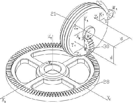
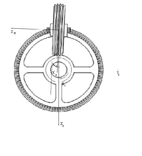
The invention provides a face gear grinding method based on a worm grinding wheel. A face gear 28, the worm grinding wheel 21, a straight gear 30 and a grinding wheel 22 for finishing a worm are adopted in the method. The face gear grinding method is characterized in that during the machining process, the face gear 28 rotates around Z-f at a constant rotating speed Wf, the worm grinding wheel 21 rotates around Zw at a constant rotating speed Ww, the straight gear 30 rotates around a Zc axis at a constant rotating speed Wc, and the grinding wheel 22 rotates around an Xt axis at a constant rotating speed Wt. During the rotation process, the tooth surface of the worm grinding wheel can be used for grinding off the tooth surface of the face gear contacted with the tooth surface so as to reach the effect of grinding the face gear; and meanwhile the worm grinding wheel 21 performs linear feed movement along the direction of the tooth width Xf of the face gear until the whole tooth profile of the face gear is completely machined. The face gear grinding method based on the worm grinding wheel provided by the invention has the beneficial effects of realizing high-precision generation of the tooth surface of the face gear, reaching the effect of high-precision machining of the face gear, and improving the comprehensive transmission performance of the face gear.
Description
technical field [0001] The invention belongs to the field of face gear numerical control milling and gear grinding in the gear manufacturing method. Background technique [0002] Face gear transmission refers to the meshing of cylindrical gear and bevel gear to realize the transmission between spatially intersecting or interlaced axes. Compared with bevel gears, face gear transmission has the advantages of large coincidence, strong bearing capacity, strong stability, small vibration, and small space occupation. With the development of aerospace industry, face gear transmission has been widely used in the power plant of aircraft and occupies a very important position. [0003] Face gear processing method is one of the main tasks of face gear research. In recent years, scholars at home and abroad have done a lot of research on it. Due to the poor bearing capacity, the application of face gears can only stay in low-speed and light-load situations, which cannot meet the transm...
Claims
Login to View More Application Information
Patent Timeline
 Patent Type & AuthorityApplications(China)
IPC IPC(8): B23F5/04B24B53/075
Inventor唐进元尹凤雷敦财邸栓虎
Owner唐进元