Light control microwave beam receiving system

A receiving system and microwave beam technology, applied in the field of microwave photonics, can solve problems such as unsuitable for practical application, large and complex system structure, etc., and achieve the effect of improving mobile communication performance, simplifying system structure, and simple system structure

Active Publication Date: 2012-04-25
TSINGHUA UNIV
View PDF5 Cites 9 Cited by
  • Summary
  • Abstract
  • Description
  • Claims
  • Application Information

AI Technical Summary

Problems solved by technology

When the number of antenna elements N and the number of directions M are large, this system needs N optical splitters, M optical combiners, and N×M delay fibers of different lengths, making the system large and complex, not suitable for practical application

Method used


Image

  • Light control microwave beam receiving system
  • Light control microwave beam receiving system
  • Light control microwave beam receiving system

Examples


Embodiment 1

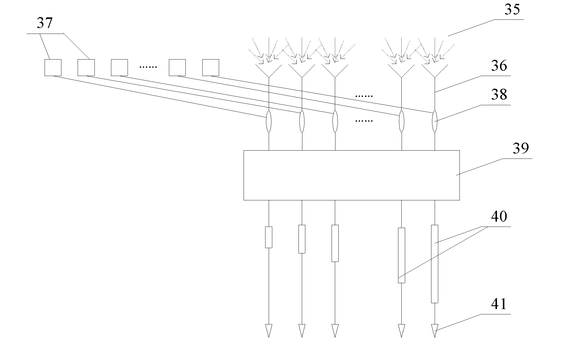
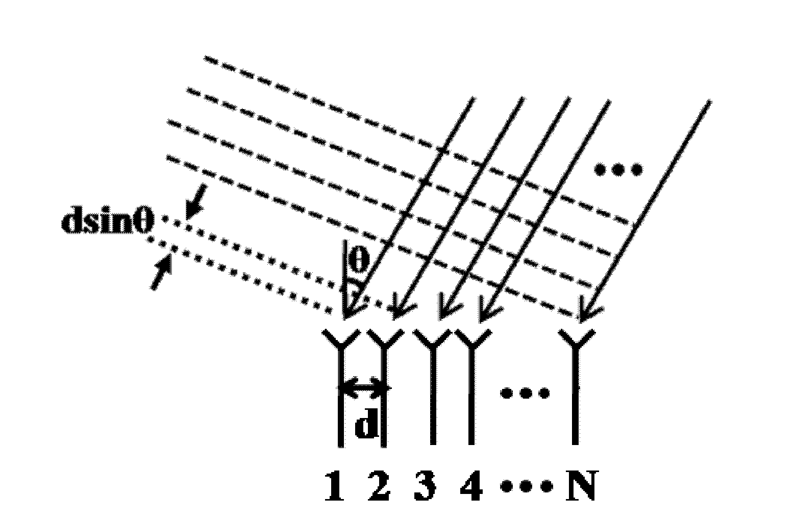
[0031] figure 2 It is a schematic structural diagram of the optically controlled microwave beam receiving system described in the first embodiment of the present invention. Such as figure 2 As shown, the system includes N antenna units 36, where N is a natural number greater than 1, for independently receiving microwave signals 35 from multiple directions in space. The N antenna units 36 are distributed on a straight line, and the same spacing is maintained between adjacent antenna units 36 .

[0032] The antenna unit 36 ​​is connected to the first input end of the optical modulator 38, the first input end is an electrical signal port, the second input end of the optical modulator 38 is connected to the laser source 37, and the second input end is Optical signal input port. The optical modulator 38 adopts a lithium niobate electro-optic modulator, receives the microwave signal 35 at the first input end, and performs intensity modulation on the laser signal coming in from ...

Embodiment 2

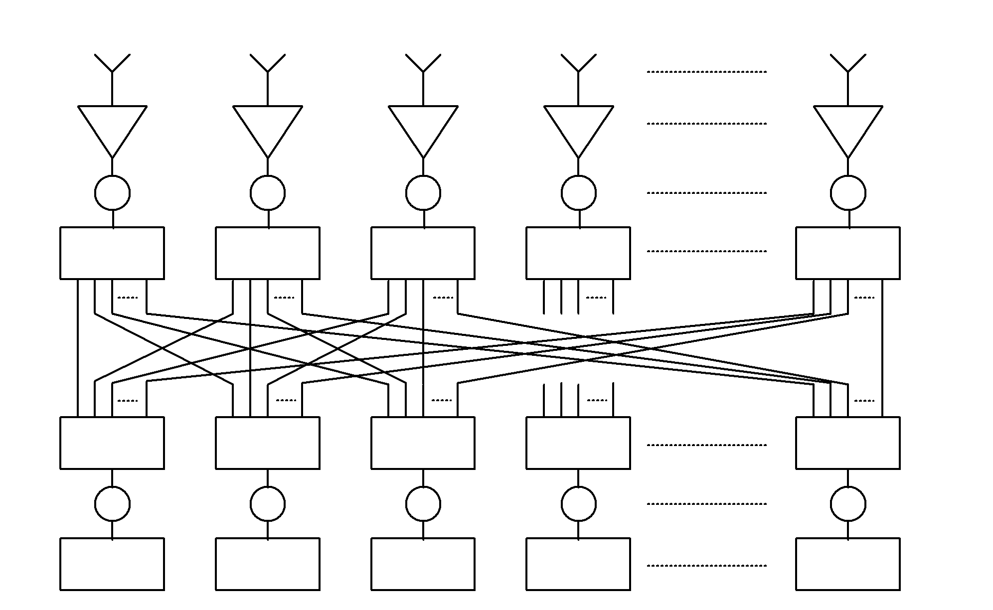
[0044] Figure 5 It is a structural schematic diagram of the optically controlled microwave beam receiving system described in the second embodiment of the present invention. Such as Figure 5 As shown, the structure of the system described in this embodiment is basically the same as that of the system described in the first embodiment. The only difference is that the optical coupler 39 is replaced by a combiner 42 and a splitter 43. combination. The combiner 42 includes N input terminals and 1 output terminal, which is used to combine and output the N optical signals output by the optical modulator 38 to the splitter 43; the splitter 43 includes 1 input terminals and M output terminals, used to receive the output of the combiner 42 and redistribute it to the M output terminals of the splitter 43.

[0045] In the optically controlled microwave beam receiving system described in the embodiment of the present invention, by using N optical modulators that output lasers of diff...


PUM


Abstract

The invention discloses a light control microwave beam receiving system, and relates to microwave photonics technology. The system comprises N antenna units, wherein each antenna unit is connected with a first input end of a photomodulator; a second input end of the photomodulator is connected with a laser source, and an output end of the photomodulator is connected with an input end of an optical signal processing unit; the optical signal processing unit comprises N input ends and M output ends, and is used for realizing the combination and redistribution of optical signals; and the M output ends of the optical signal processing unit are respectively connected with light delayed units with different length, and the time-delay quantity generated by the light delayed units to the wavelength interval of laser output by adjacent laser light sources just compensates the time-delay quantity generated by the microwave signals on the adjacent antenna units due to source direction. The system disclosed by the invention has the advantages that the system structure is simple, high data rate and multi-user requirements are satisfied, and the mobile communication performance is improved.

Description

technical field [0001] The invention relates to the technical field of microwave photonics, in particular to an optically controlled microwave beam receiving system. Background technique [0002] In recent years, with the continuous development of mobile communications, the number of mobile users has increased dramatically, and data services have gradually evolved into multimedia services, resulting in a sharp increase in system information capacity and bandwidth. Communication systems that receive microwave signals are in increasing demand. [0003] The traditional PAA (Phase Array Antenna, Phased Array Antenna) system can realize the reception of multi-directional microwave signals. Interferometric superposition of signal waves from small antenna elements enables directional output and scanning. However, the tilt of the beam makes the PAA system have a principle limit in the application of broadband microwave, which cannot meet the needs of modern economic construction. ...

Claims


Application Information

Patent Timeline
Patent Type & Authority Applications(China)
IPC IPC(8): H01Q3/34
Inventor 罗毅赵湘楠石拓熊兵孙长征
Owner TSINGHUA UNIV
Why Eureka
Try Eureka