
Construction method for upstream-side wall body of semi-underground power station plant

A side wall, underground type technology, applied in the directions of hydropower stations, buildings, hydropower generation, etc., can solve the problems of difficulty in meeting the operation requirements of the bridge cranes of the power station, large displacement of the upstream side wall, and increased construction costs, and achieve a good operating environment. , low cost, small size effect

Inactive Publication Date: 2012-05-02
YELLOW RIVER ENG CONSULTING
View PDF5 Cites 6 Cited by
  • Summary
  • Abstract
  • Description
  • Claims
  • Application Information

AI Technical Summary

Problems solved by technology

According to the design and construction specifications, the underground wall structure is provided with a deformation joint every 20m-30m. When the side wall is under the action of horizontal load when the joint is divided, the displacement of the upstream side wall is too large, which is difficult to meet the operation requirements of the bridge crane of the power station.
In order to meet the operation requirements of the bridge crane in the power station, the wall is currently thickened and a large number of structural steel bars are arranged, which greatly increases the construction cost

Method used


Image

  • Construction method for upstream-side wall body of semi-underground power station plant
  • Construction method for upstream-side wall body of semi-underground power station plant
  • Construction method for upstream-side wall body of semi-underground power station plant

Examples


Embodiment Construction

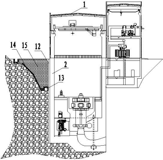
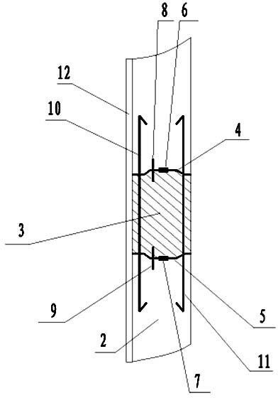
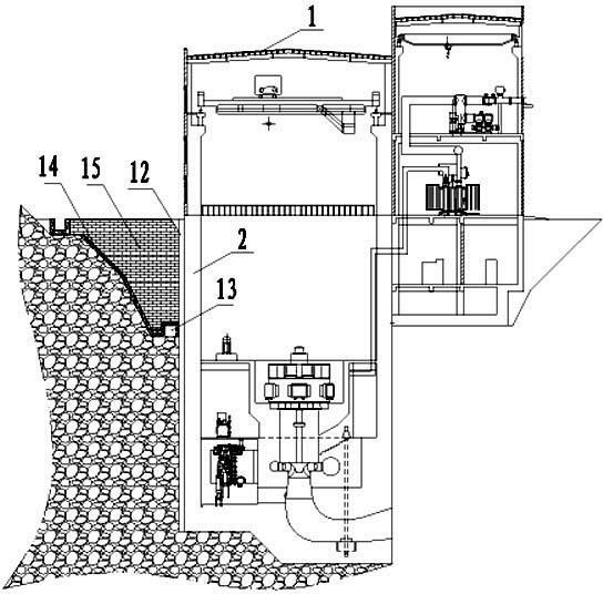
[0013] Such as figure 1 , 2 As shown, the construction method of the upstream side wall of the semi-underground power station building in the present invention includes building a power station building 1 with a concrete structure on the bank of the downstream river bank of the dam water diversion system, and the power station building 1 is embedded in the rock wall part underground. The longitudinal center line of the upstream side wall 2 is poured with post-cast compensating concrete, that is, the post-cast strip 3; the thickness of the post-cast strip 3 is consistent with that of the upstream side wall, and the width is 2 meters; the post-cast strip 3 and the corresponding upstream side wall Steel wire meshes 4 and 5 are respectively arranged on the contact surface of the body 2, and water-swellable water-stop strips 6 and 7 are respectively arranged along the longitudinal centerline of each piece of steel mesh 4 and 5; Copper water-stop sheets 8 and 9 are arranged respect...


PUM


Abstract

The invention discloses a construction method for an upstream-side wall body of a semi-underground power station plant, comprising a power station plant with a concrete structure, wherein a rear pouring zone is poured along the longitudinal middle line of the upstream-side wall body positioned on the underground part of the power station plant; steel wire meshes are distributed on the contact surface of the rear pouring zone and the corresponding upstream-side wall body; water-swelling water seals are respectively distributed along the longitudinal line of each steel wire mesh; red copper water seal sheets are respectively distributed on the joint of the rear pouring zone and the corresponding upstream-side wall body; multiple layers of butted seam reinforcing steel bars are distributed from bottom to top in the upstream-side wall body and are distributed in a mode of horizontally penetrating through the rear pouring zone; before the upstream-side wall body is poured, a polyethylene closed-cell foam plate is arranged on the outer surface of the upstream-side wall body; drain tanks are distributed along the bottom of the upper outside backfilling groove of the upstream-side wall body; sand-free concrete cushion plies are respectively spread on the bottom and the side surface of the backfilling groove; and concrete blocks are backfilled to the backfilling groove. The semi-underground power station plant built with the construction method has the advantages of simple structure, safety and reliability, low cost, small size of a power station plant structure and the like.

Description

technical field [0001] The invention relates to the powerhouse structure of a power station, in particular to a construction method of the upstream side wall of a semi-underground powerhouse and the design of an external drainage system. Background technique [0002] The embedded rock wall of the upstream side wall of the semi-underground power plant is generally arranged on the bank of the river downstream of the water diversion system, which is a form of power plant often used in the design of hydropower plants. For the semi-underground power plant, due to its equipment requirements, it is generally a large-span (30m-80m) and high side wall (20m-30m) structure. The main force-bearing structure of the power station is located below the ground, and has the characteristics of high groundwater level, high water pressure, and lack of constraints on the side walls above the generator floor. According to the design and construction specifications, a deformation joint is set ever...

Claims


Application Information

Patent Timeline
Patent Type & Authority Applications(China)
IPC IPC(8): E02B9/00E02D29/05
CPCY02E10/22Y02E10/20
Inventor 柴志阳孟旭央史仁杰熊卫翟利军段世超
Owner YELLOW RIVER ENG CONSULTING
Learn More