Deep-ultraviolet lithography illumination system

A lighting system and deep ultraviolet light technology, applied in the field of high-resolution lithography, can solve the problems of complex technology, high price, and difficult research of lithography technology, and achieve good lighting effects, simple results, and avoid damage

Active Publication Date: 2013-06-19
BEIJING INSTITUTE OF TECHNOLOGYGY
View PDF4 Cites 0 Cited by
  • Summary
  • Abstract
  • Description
  • Claims
  • Application Information

AI Technical Summary

Problems solved by technology

However, due to its complex technology and high price, it brings difficulties to the research of lithography technology.

Method used


Image

  • Deep-ultraviolet lithography illumination system
  • Deep-ultraviolet lithography illumination system
  • Deep-ultraviolet lithography illumination system

Examples


Embodiment Construction

[0035] The lithography illumination system of the present invention will be further described in detail below in conjunction with the accompanying drawings.

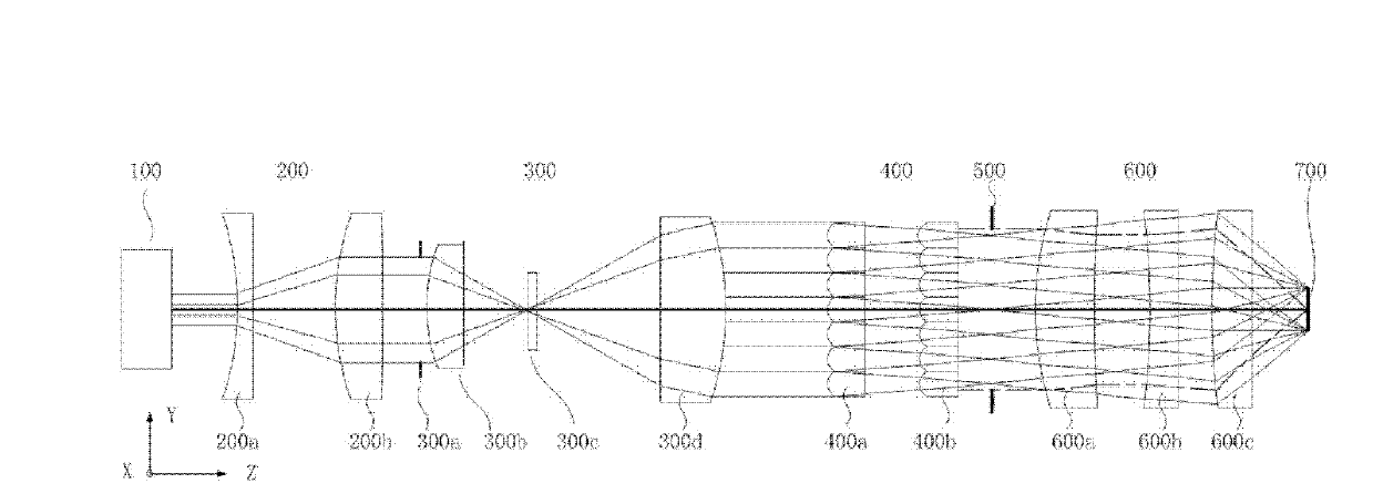
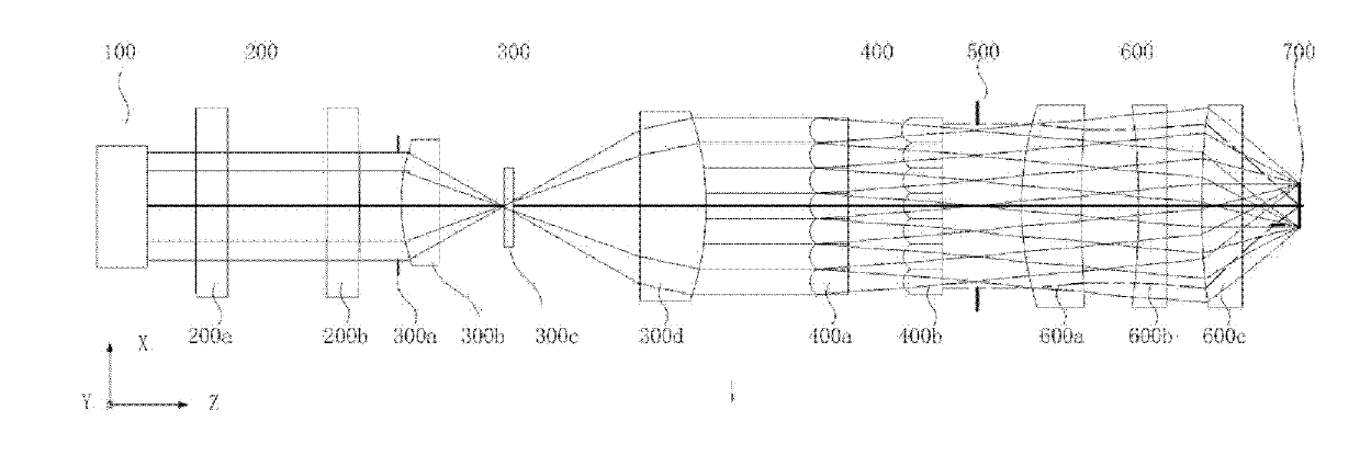
[0036] Predefinition of the coordinate system: the direction of the laser beam is taken as the Z axis, and the coordinate system (X, Y, Z) is established according to the principle of the left-handed coordinate system.

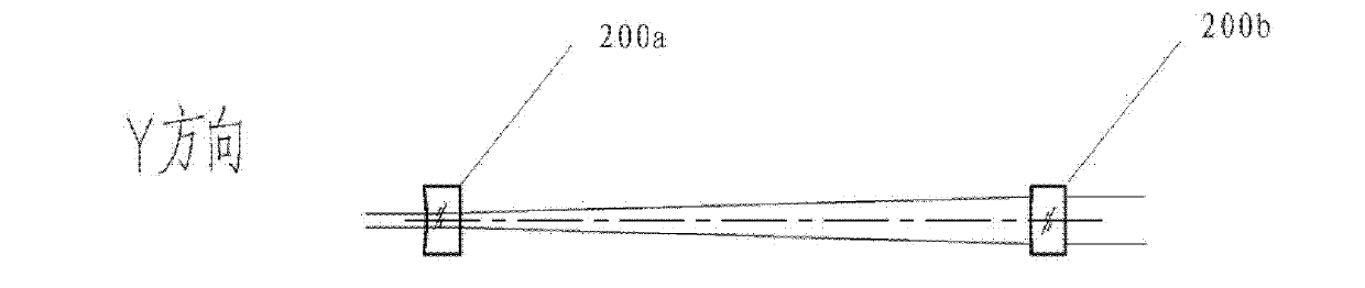
[0037] Such as Figure 1A with 1B As shown, the deep ultraviolet lithography illumination system of the present invention includes a deep ultraviolet laser light source, a cylindrical beam expander mirror system, a spherical beam expander mirror system, a compound eye uniform photon system, a condenser mirror system, a circular diaphragm and an aperture diaphragm; The sequence relationship of each component along the forward direction of the laser light path is: deep ultraviolet laser light source, cylindrical beam expander mirror system, circular diaphragm, spherical beam expander mirror system, compoun...


PUM


Abstract

The invention provides a deep-ultraviolet lithography illumination system which comprises a deep-ultraviolet laser source, a cylindrical beam expander sub-system, a spherical beam expander sub-system, a compound eye light evening sub-system, a condenser sub-system, a round diaphragm and an aperture diaphragm, wherein the order of the components along the advancing direction of the laser path is as follows: the deep-ultraviolet laser source, the cylindrical beam expander sub-system, the round diaphragm, the spherical beam expander sub-system, the compound eye light evening sub-system, the aperture diaphragm and the condenser sub-system; the aperture diaphragm is located on the front focal surface of the condenser sub-system; and the centers of the components are superposed with the center of a laser beam. The deep-ultraviolet lithography illumination system provided by the invention adopts a simple spherical and cylindrical structure, and can meet the requirements of a lithography illumination system.

Description

technical field [0001] The invention relates to a deep ultraviolet lithography illumination system, which belongs to the technical field of high-resolution lithography. Background technique [0002] Photolithography is a technology for manufacturing semiconductor devices, which uses optical methods to transfer the circuit pattern on the mask to the silicon wafer. Photolithography technology uses deep ultraviolet light source, such as ultraviolet (UV), deep ultraviolet (DUV) and so on. A variety of semiconductor devices can be fabricated using photolithography, such as diodes, transistors, and VLSI. A typical lithography exposure system includes illumination system, mask, projection objective lens and silicon wafer. The lighting system can realize uniform lighting on the mask. Now, with the continuous reduction of the feature size of semiconductor products, various resolution enhancement technologies, such as off-axis illumination technology and polarized illumination tech...

Claims


Application Information

Patent Timeline
Patent Type & Authority Patents(China)
IPC IPC(8): G03F7/20G02B27/00G02B27/09G02B27/28G02B3/00G02B3/06
Inventor 李艳秋魏立冬
Owner BEIJING INSTITUTE OF TECHNOLOGYGY
Why Eureka
Try Eureka