Encapsulated inductor and assembly process thereof

An assembly process, inductance technology, applied in the direction of inductance/transformer/magnet manufacturing, transformer/inductor coil/winding/connection, circuit, etc., can solve the problem of manufacturing, assembly, transportation, increase in volume and weight of inductance, and explosion of inductance and other problems, to achieve the effect of meeting the needs of high-pressure work, low processing and manufacturing costs, and firm structure

Active Publication Date: 2012-05-02
GLORYMV ELECTRONICS
View PDF2 Cites 11 Cited by
  • Summary
  • Abstract
  • Description
  • Claims
  • Application Information

AI Technical Summary

Problems solved by technology

[0002] With the development of science and technology, the application of inductors in circuits is very common, and their types and shapes tend to be diversified, with higher precision, more beautiful appearance, and safer and more reliable; however, many inductors can work under high voltage conditions, but cannot Work normally under the impact of high current and instantaneous high current; under the impact of high current or instantaneous high current, the inductance may even explode; for example, the inductance is 20-30kV, the average current is hundreds of amperes, and the instantaneous current is 2,000 amperes work in high voltage circuits above
At present, in the applicatio...

Method used


Image

  • Encapsulated inductor and assembly process thereof
  • Encapsulated inductor and assembly process thereof
  • Encapsulated inductor and assembly process thereof

Examples


Embodiment Construction

[0023] The specific implementation manner of the present invention will be described in further detail below by describing the best embodiment with reference to the accompanying drawings.

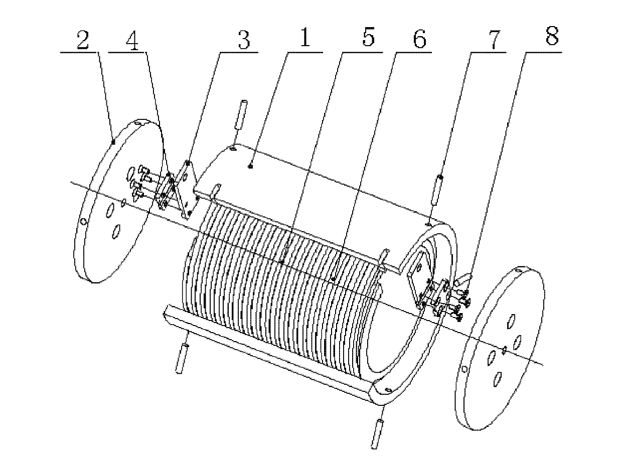
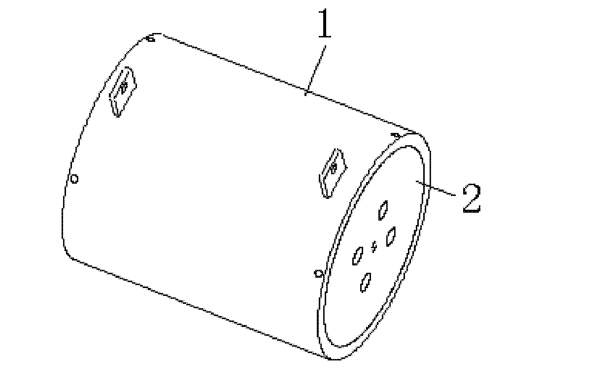
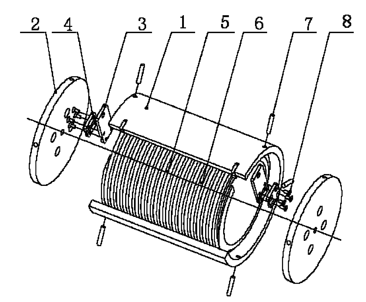
[0024] Such as figure 1 and figure 2 As shown, the potting inductor includes a cylindrical skeleton 6 and a cylindrical protective cover 1 wound with a copper coil 5 on the surface, the skeleton 6 is located inside the protective cover 1, and the skeleton 6 is concentric with the protective cover 1; The cover 1 is provided with an outlet for the copper wire of the copper coil 5 to protrude; the two ends of the inner frame 6 of the protective cover 1 are respectively provided with a bus bar 3, and the two ends of the copper coil 5 are respectively stuck on the bus bar 3, There is a wire groove on the busbar 3; an end cover plate 2 is provided on both ends of the protective cover 1, and a pressure plate 4 is provided between the end cover plate 2 and the bus bar 3, and the pressure plate 4 ...


PUM


Abstract

The invention discloses an encapsulated inductor and an assembly process thereof. The encapsulated inductor comprises a framework and a protective cover, wherein the surface of the framework is wound with a copper wire coil; the framework is arranged in the protective cover, and the framework and the protective cover are concentric; the protective cover is provided with a wire outlet used for extending a copper wire of the copper wire coil; both ends of the framework in the protective cover are provided with a bus bar respectively, and both ends of the copper wire coil are clamped on the bus bars respectively; both ends of the protective cover are provided with an end cover plate respectively; pressing plates are arranged between the end cover plates and the bus bars and are connected with the bus bars; the protective cover is provided with insulating pins; and cured epoxy resin layers are arranged at contact positions of the protective cover and the end cover plates, at contact positions of the insulating pins and the protective cover, between the framework and the end cover plates, and between the outer surface of the framework and the inner wall of the protective cover. The assembly process of the encapsulated inductor comprises three steps. The encapsulated inductor can meet the operational requirements on high voltage and high current/instantaneous high current impact, and is low in manufacturing cost, safe and reliable.

Description

technical field [0001] The invention relates to a high-voltage and high-current inductor, in particular to a potting inductor and an assembly process thereof. Background technique [0002] With the development of science and technology, the application of inductors in circuits is very common, and their types and shapes tend to be diversified, with higher precision, more beautiful appearance, and safer and more reliable; however, many inductors can work under high voltage conditions, but cannot Work normally under the impact of high current and instantaneous high current; under the impact of high current or instantaneous high current, the inductance may even explode; for example, the inductance is 20-30kV, the average current is hundreds of amperes, and the instantaneous current is 2,000 amperes Work in the above high voltage circuit. At present, in the application of inductors, the diameter of the inductor winding is usually increased to meet the demand of large current or ...

Claims


Application Information

Patent Timeline
IPC IPC(8): H01F27/30H01F27/29H01F41/00
Inventor 李成宫龙刘林程辉
Owner GLORYMV ELECTRONICS
Why Eureka
Try Eureka