Power supply connecting device of double-end gas discharge lamp

A gas discharge lamp and power supply connection technology, applied to discharge lamps, discharge tubes, circuits, etc., can solve the problems of easy dispersal, unsafe use, and glass breakage, etc., to achieve convenient installation and use, prolong service life, and reduce heat generation The effect of the phenomenon

Inactive Publication Date: 2012-05-02
NINGBO YAMAO OPTOELECTRONICS CO LTD
View PDF6 Cites 3 Cited by
  • Summary
  • Abstract
  • Description
  • Claims
  • Application Information

AI Technical Summary

Problems solved by technology

[0002] Patent No. CN201020273628.6 "High Power Gas Discharge Lamp for Plant Lighting" is connected to the power supply with the thread on the lamp head end. Although it is convenient to use, the working temperature of the gas discharge lamp is high. After working for a long time, the lamp head is easy to heat up and become black and loose , it is not safe to use
[0003] Patent No. CN201020271581.X "Double-ended high-power high-pressure sodium lamp" also discloses a connection device with the power supply. The two ends of the light source are connected to the molybdenum rods, and the molybdenum sheets are arranged at the two ends of the glass bulb at the flattened air-tight joints. They are respectively connected to molybdenum rods and lead wires made of multi-strand metal guide wires. Because the flattened airtight joint connected to the power supply is a glass part with low thermal conductivity and low mechanical strength, the glass at the end is easily broken after long-term high-temperature operation. , directly connected to the power supply with lead wires, the contact surface of a single bundle of wires is small, the capacitance is small, easy to loose, easy to break, easy to deform, unreliable connection, and unsafe to use

Method used


Image

  • Power supply connecting device of double-end gas discharge lamp
  • Power supply connecting device of double-end gas discharge lamp
  • Power supply connecting device of double-end gas discharge lamp

Examples


Embodiment Construction

[0012] Embodiments of the present invention will be further described in detail below in conjunction with the accompanying drawings.

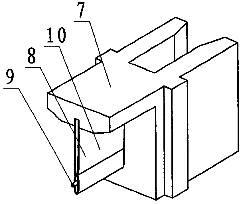
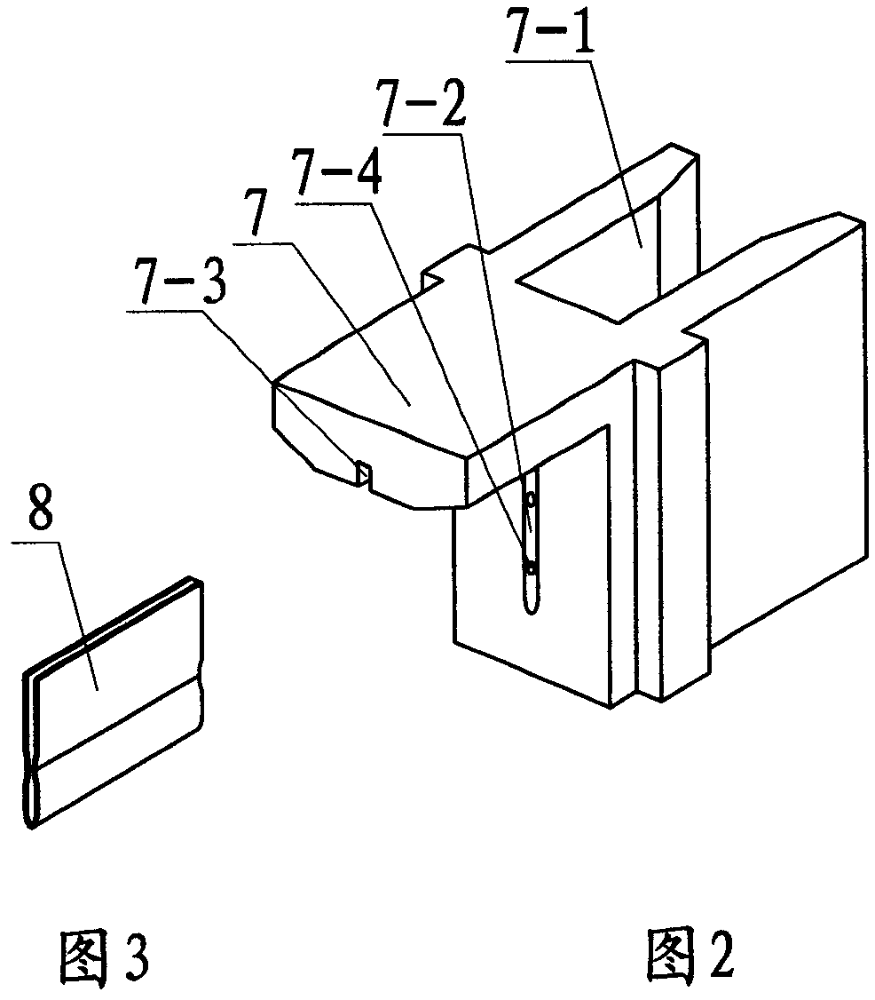
[0013] The lead-out wire clip 10 is made of a stainless steel sheet and has a clip 8 with indentations on both surfaces. The outer end of the lead-out wire 9 is clamped and fixed in the middle gap to form a whole. Add spot welding to the clip 8 on the outer surface of the lead wire, so that the lead wire is completely fixed on the clip, such as figure 1 , image 3 , Figure 5 shown.

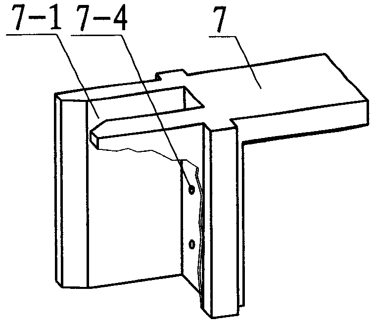
[0014] Porcelain head 7 is made of insulating material with high temperature resistance, moisture resistance and high dielectric strength. There are short grooves 7-2 on the left vertical surface of the porcelain head, long grooves 7-1 on the right surface, and the bottom surface of the long grooves Two threading holes 7-4 are arranged on the vertical surface and communicate with the short groove 7-2, and the upper surface has a lower groove 7-3, such as figur...


PUM


Abstract

The invention discloses a power supply connecting device of a double-end gas discharge lamp. The connecting device comprises a molybdenum piece used for fixing a squashing hermetic seal section on the two ends of a lamp tube, and the molybdenum piece is respectively connected with a molybdenum rod and an educing wire; the educing wire is clamped among clamping pieces so as to form an outgoing line clamping piece, a porcelain head is respectively fixed on the squashing hermetic seal sections on the two ends of the lamp tube, and the outgoing line clamping piece is fixed on the porcelain head; an integral outgoing line clamping piece is directly inserted in a power socket, the contact surface is large, the electric property is good, the mechanical strength is high, thereby greatly reducing an exothermic phenomenon; the other end of the outgoing line clamping piece is arranged in an insulation porcelain head which is heat-resisting moisture-proof and high dielectric strength, and a groove is arranged in the porcelain head and matched with the squashing hermetic seal section on the two ends of the lamp tube; and the glass part is not easy to crack, the service life of the discharge lamp is greatly prolonged, defects that the original power supply connecting device is easy to heat and transform, and the glass is easy to crack are improved, and the use is safe and reliable.

Description

technical field [0001] The invention relates to a connection between a gas discharge lamp and a power supply, in particular to a power supply connection device for a double-ended gas discharge lamp. Background technique [0002] Patent No. CN201020273628.6 "High Power Gas Discharge Lamp for Plant Lighting" is connected to the power supply with the thread on the lamp head end. Although it is convenient to use, the working temperature of the gas discharge lamp is high. After working for a long time, the lamp head is easy to heat up and become black and loose , which is not safe to use. [0003] Patent No. CN201020271581.X "Double-ended high-power high-pressure sodium lamp" also discloses a connection device with the power supply. The two ends of the light source are connected to the molybdenum rods, and the molybdenum sheets are arranged at the two ends of the glass bulb at the flattened air-tight joints. They are respectively connected to molybdenum rods and lead wires made ...

Claims


Application Information

Patent Timeline
Patent Type & Authority Applications(China)
IPC IPC(8): H01J5/62
Inventor 陈晖施振家
Owner NINGBO YAMAO OPTOELECTRONICS CO LTD
Why Eureka
Try Eureka