Apparatus for removing iron in powder

A powder and box technology is applied in the field of powder iron removal devices, which can solve the problems of energy consumption in the cooling system, fine powder entering the iron removal port, and difficulty in applying iron removal, so as to achieve a small occupied space and a good iron removal effect. , the effect of simple structure

Active Publication Date: 2012-05-09
洛阳宜墨新材料有限公司
View PDF8 Cites 12 Cited by
  • Summary
  • Abstract
  • Description
  • Claims
  • Application Information

AI Technical Summary

Problems solved by technology

However, the electromagnetic separator relies on current to generate a magnetic field, which consumes a lot of power during use, and its cooling system also consumes energy.
The permanent magnetic iron remover is composed of rare earth magnetic materials NdFeB and ferrite with high coercive force and high remanence as a magnetic source to form a strong magnetic field for absorbing ferromagnetic debris. The whole machine is not powered on and has no energy consumption. , but the existing iron removal devices of this type are not only complex in structure, but most of them are difficult to apply to iron removal of powder materials. A large waste of raw materials; the structure of the pipeline type iron remover can not completely disperse the powder, the efficiency of iron removal is low, and a large amount of powder is carried into the tap hole

Method used


Image

  • Apparatus for removing iron in powder
  • Apparatus for removing iron in powder

Examples


Embodiment 1

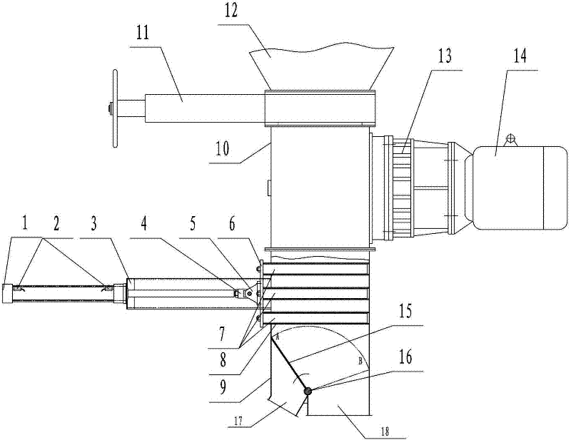
[0019] Example 1 A powder iron removal device, see figure 1 , including a feeding mechanism, a magnetic separation mechanism and a support, the magnetic separation mechanism includes a box body, three sets of magnetic rod groups 7 equidistantly distributed up and down (the number of magnetic rods in each magnetic rod group decreases successively from top to bottom, each The magnetic rods in the group (made of NdFeB magnets, whose magnetic strength is not less than 12000Gs, and whose intrinsic coercivity ≥ 14kOe) are distributed symmetrically and equidistantly along the center line of the box), and magnetic Magnetic rod casing (thin-walled stainless steel casing) corresponding to the number of rods, magnetic rod group drive unit, flap valve, PLC controller, the feeding mechanism includes a rigid impeller feeder 10, a reducer 13, a motor 14. Motor frequency converter (control the motor speed to adjust the size of the feeding amount, not shown in the figure) and the feeding bin 1...


PUM


Abstract

The invention relates to an apparatus for removing iron in powder. The apparatus comprises a feeding mechanism, a magnetic separation mechanism and a support; the magnetic separation mechanism comprises a box, at least a magnetic rod set, magnetic rod sleeves with an amount corresponding to the amount of magnetic rods, a magnetic rod set driving unit and a flap valve, wherein, the magnetic rod sleeves are transversely arranged at the middle and upper parts of the box, one end of every magnetic rod of the magnetic rod set is fixed by a connection board and is then connected with a power output terminal of the magnetic rod set driving unit, the other end of every magnetic rod passes through a corresponding magnetic rod sleeve, every magnetic rod slidely moves in its corresponding magnetic rod sleeve under the driving of the magnetic rod set driving unit, an iron discharging outlet and a material discharging outlet are arranged at the bottom of the box, and the flap valve is installed above the iron discharging outlet and the material discharging outlet. The apparatus has the following advantages: a good iron-moving effect, low energy consumption, low cost for operation and maintenance, particular suitability for fine removal of iron in a powder material, a simple structure, small occupation space, convenient fabrication, installation and maintenance, a low price and easy popularization and usage.

Description

technical field [0001] The invention relates to iron removal equipment, in particular to a powder iron removal device. Background technique [0002] According to different sources of magnetic force, iron remover can be divided into electromagnetic iron remover and permanent magnet iron remover. The electromagnetic iron remover is essentially a DC electromagnet, and its excitation coil generates a strong magnetic field during the electrification process to attract iron parts in non-magnetic materials. For example, an electromagnetic powder iron remover is disclosed in Chinese patent document CN1 01342515A . However, the electromagnetic separator relies on electric current to generate a magnetic field, which consumes a large amount of electric energy during use, and its cooling system also consumes energy. The permanent magnetic iron remover is composed of rare earth magnetic materials NdFeB and ferrite with high coercive force and high remanence as a magnetic source to fo...

Claims


Application Information

Patent Timeline
Patent Type & Authority Applications(China)
IPC IPC(8): B03C1/26
Inventor 张全利赵稳成
Owner 洛阳宜墨新材料有限公司
Why Eureka
Try Eureka