Transformer with high set-up ratio, solar inverter and solar battery system

A high boost ratio, converter technology, applied in battery circuit devices, control/regulation systems, AC power input conversion to DC power output, etc., can solve the problem of small boost ratio, low energy conversion efficiency, long transmission path, etc. question

Inactive Publication Date: 2012-05-09
LEADSOLAR ENERGY
View PDF8 Cites 15 Cited by
  • Summary
  • Abstract
  • Description
  • Claims
  • Application Information

AI Technical Summary

Problems solved by technology

[0010] In the process of realizing the present invention, the inventor found that there are at least defects such as small boost ratio, long transmission path, large extra loss and low energy conversion efficiency in the prior art

Method used


Image

  • Transformer with high set-up ratio, solar inverter and solar battery system
  • Transformer with high set-up ratio, solar inverter and solar battery system
  • Transformer with high set-up ratio, solar inverter and solar battery system

Examples


Embodiment 1

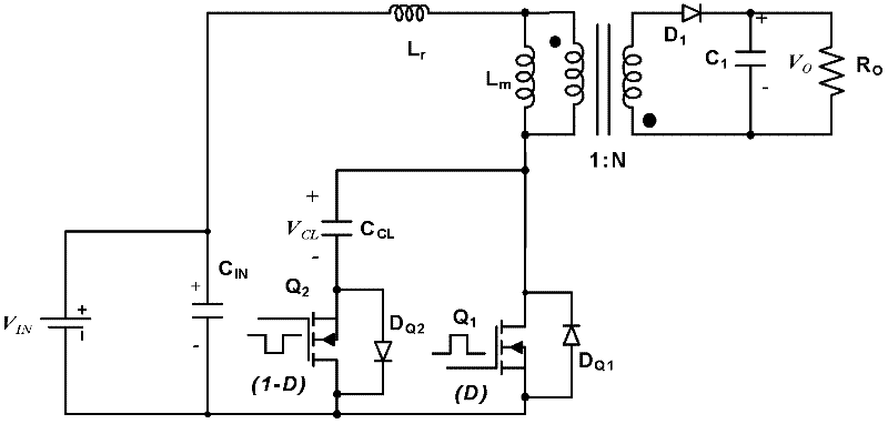
[0093] According to an embodiment of the present invention, a high boost ratio converter is provided. Such as Figure 3a As shown, this embodiment includes a DC input power supply, a half-wave rectifier capacitor , the clamp capacitor , the transformer, the magnetizing inductance of the primary side of the transformer , the resonant inductance , power semiconductor switch and , body diode or an additional parallel diode and , output resistance , transformer secondary rectifier diode , transformer secondary side filter capacitor , and the bypass capacitor and .

[0094] Among them, the positive pole of the above-mentioned DC input power supply is connected to the beginning end of the primary side coil of the transformer; After that, it is connected with the beginning of the transformer secondary coil and the transformer secondary rectifier diode Cathode, power semiconductor switch the drain, body diode or an additional parallel diode the cat...

Embodiment 2

[0099] According to an embodiment of the present invention, a high boost ratio converter is provided. Such as Figure 3b As shown, this embodiment includes a DC input power supply, a full-wave rectifier capacitor , the clamp capacitor , the transformer, the magnetizing inductance of the primary side of the transformer , the resonant inductance , power semiconductor switch and , and body diode or an additional parallel diode and , output resistance , transformer secondary rectifier diode and , transformer secondary side filter capacitor and , and the bypass capacitor and .

[0100] Among them, the positive pole of the above-mentioned DC input power supply is connected to the beginning end of the primary side coil of the transformer; After, with transformer secondary side rectifier diode The anode of the transformer, the beginning of the transformer secondary coil, the transformer secondary rectifier diode Cathode, power semiconductor switc...

Embodiment 3

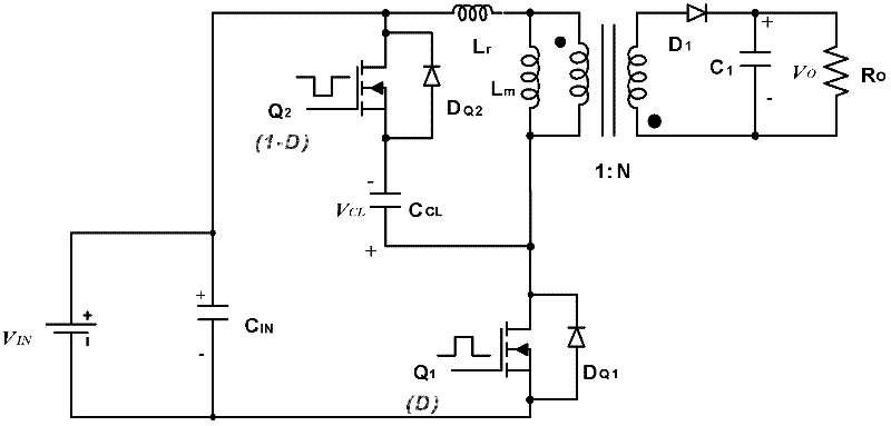
[0106] According to an embodiment of the present invention, a high boost ratio converter is provided. Such as Figure 3c As shown, this embodiment includes a DC input power supply, a half-wave rectifier capacitor , the clamp capacitor , the transformer, the magnetizing inductance of the primary side of the transformer , the resonant inductance , power semiconductor switch and , and body diode or an additional parallel diode and , output resistance , and the transformer secondary rectifier diode , transformer secondary side filter capacitor , and the bypass capacitor and .

[0107] Among them, the positive pole of the above-mentioned DC input power supply is connected to the beginning end of the primary side coil of the transformer; After that, it is connected with the beginning of the transformer secondary coil and the transformer secondary rectifier diode Cathode, power semiconductor switch the drain, body diode or an additional parallel d...


PUM


Abstract

The invention discloses a transformer with a high set-up ratio, a solar inverter and a solar battery system. According to the invention, the low output voltages of power sources are converted to high output voltages through the transformer with the high set-up ratio; and according to the specific application and different control methods, the outputs of the transformer with the high set-up ratio from a first technical scheme to a fourth technical scheme can be standard direct current voltages or controlled and modulated specific voltage wave forms. By using the transformer with the high set-up ratio, the solar inverter and the solar battery system, the defects of small set-up ratio, long transmission path, large additional loss, low energy conversion efficiency and the like in the prior art can be overcome, so as to realize the advantages of large set-up ratio, short transmission path, small additional loss and high energy conversion efficiency.

Description

technical field [0001] The invention relates to the technical field of boosting circuit and grid-connected solar power generation, in particular, to a converter with a high boosting ratio, a solar inverter and a solar battery system. Background technique [0002] In recent years, renewable energy power generation systems based on wind energy and solar energy have been used more and more in the world. For solar grid-connected power generation systems, in addition to the current mainstream concentrated high-power solar power plants, distributed solar grid-connected power generation systems, because they can optimize the working status of solar panels, can improve the system's annual life in most cases. Power generation has been paid more and more attention and has become a research hotspot. [0003] Among them, the distributed power generation system based on solar micro-inverters is particularly eye-catching and widely used in the United States. The core of the solar micro-...

Claims


Application Information

Patent Timeline
Patent Type & Authority Applications(China)
IPC IPC(8): H02M3/335H02J3/38H02M7/5387H02J7/00
CPCY02E10/563Y02E10/56
Inventor 梁志刚郑崇峰
Owner LEADSOLAR ENERGY
Why Eureka
Try Eureka