
Rotationally driven multi-bevel step tool

A rotary drive, margin technology, used in step drills, tools for lathes, manufacturing tools, etc., can solve the problems of chip blocking and small chip removal volume.

Inactive Publication Date: 2012-05-09
GUEHRING OHG
View PDF10 Cites 11 Cited by
  • Summary
  • Abstract
  • Description
  • Claims
  • Application Information

AI Technical Summary

Problems solved by technology

[0004] Traditional multi-land step tools have the following disadvantages: the volume for chip evacuation in each flute tends to be relatively small, so under unfavorable conditions, chip jamming can easily occur in the area of ​​the cutting stage with a relatively small machining diameter

Method used


Image

  • Rotationally driven multi-bevel step tool
  • Rotationally driven multi-bevel step tool
  • Rotationally driven multi-bevel step tool

Examples


Embodiment Construction

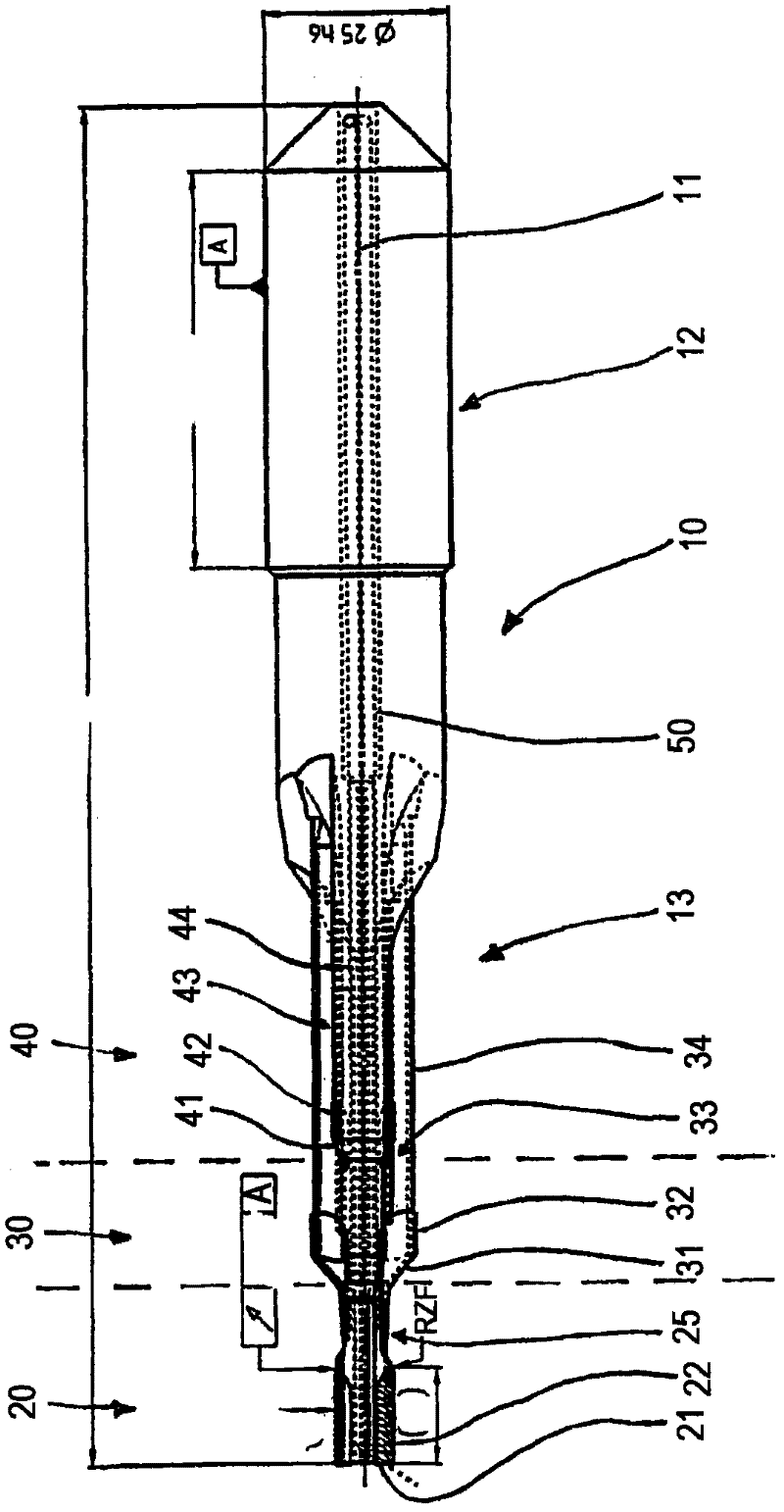
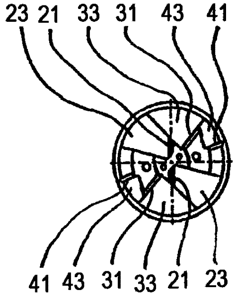
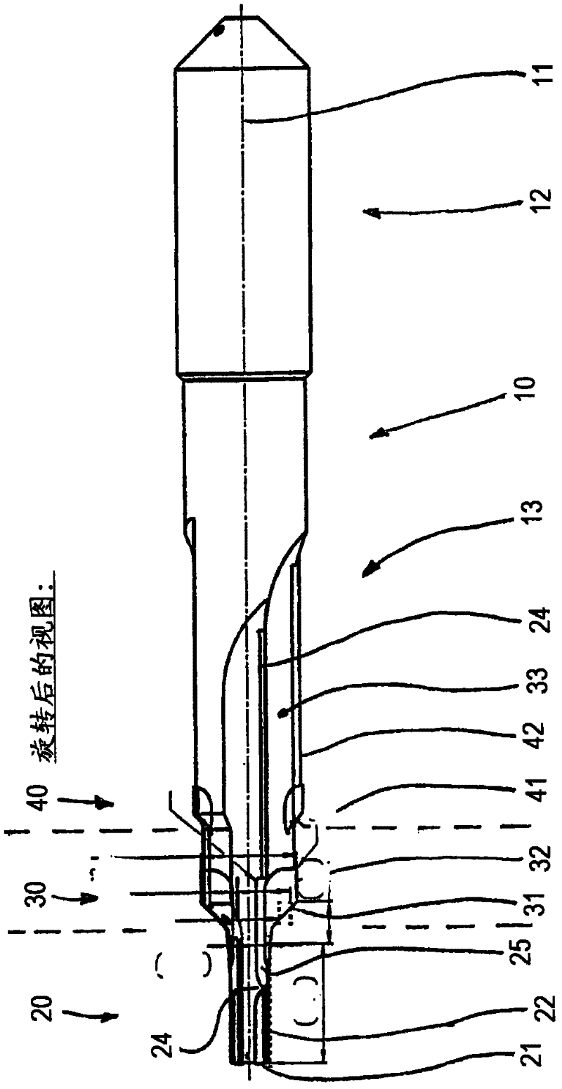
[0033] Reference numeral 10 in the drawings indicates a rotary driven multi-edge cutting multi-margin step tool in the form of a step drill. The step drill 10 is used to make a step hole, such as a fuel injector hole for installing a fuel injector on a cylinder block in the automobile industry. It should be pointed out that the dimensional and machining data contained in the figures relate only to one embodiment of a multi-land stepped tool.

[0034] Step drill 10 has a shank 12 and a cutting portion 14 for clamping in a chuck (not shown). The length of the stepped drill 10 is, for example, about 191.5 mm, and the diameter of the shank is about 25 mm. In the illustrated embodiment, the stepped drill 10 has three cutting stages 20, 30 and 40, wherein the first cutting stage 20 has a nominal diameter D20 and the second cutting stage 30 has a nominal diameter D30 slightly larger than that of the first cutting stage. The nominal diameter, the nominal diameter D40 of the third cu...


PUM


Abstract

The invention relates to a rotationally driven multi-bevel step tool, particularly a step drill for drilling into solid material, comprising a plurality of one-edged or multi-edged cutting steps which are arranged in a staggered manner in the cutting and advancing directions and each have a number of flutes that corresponds to the number of edges. Flutes (23, 33) adjoining each other in the circumferential direction are separated from each other by a web (24). According to the invention, the flues (23, 33) adjoining each other in the circumferential direction of two consecutive cutting steps (20, 30) in the cutting and advancing directions are connected to each other by a metal-cutting window (25) that is open on the circumferential side and interrupts the interposed web (24).

Description

technical field [0001] The invention relates to a rotary-driven stepped tool according to the preamble of claim 1, in particular a stepped drill for drilling holes in solid materials, said rotary-driven stepped tool comprising a plurality of cutting edges and Single or multiple cutting stages with staggered feed directions. Background technique [0002] Multi-level processing often occurs in manufacturing technology. For example, it is necessary to manufacture a plurality of axially staggered holes of different diameters, but it is often necessary to ream the holes after drilling or perform different drilling and reaming treatments. In order to minimize the machining time, combined tools have been developed that can perform the above-mentioned different processes in one process. Such combination tools include step drills, drilling reamers, step reamers, step reamers, etc., and these tools are collectively referred to as step tools hereinafter (where appropriate). [0003]...

Claims


Application Information

Patent Timeline
Patent Type & Authority Applications(China)
IPC IPC(8): B23B51/00
CPCB23B51/009B23B2251/406B23B51/06B23B2220/04B23B2226/315B23B2250/12Y10T408/45Y10T408/455Y10T408/78Y10T408/81Y10T408/906Y10T408/9095
Inventor L・博兹库尔特
Owner GUEHRING OHG
Learn More