


Quick Research
Generate reliable direction feasibility study reports for your R&D in just a few steps.

Technical Q&A
Discover and master advanced knowledge NOW. Basics, ideas, possibilities, all at once.

Find Solutions
As an expert in R&D theories, this can generate solutions to your technical problems instantly.

Evaluate Feasibility
Analyze your overall solution with one click, know your potential R&D risks in advance.

Monitor Landscape
Get weekly tech updates, stay abreast of the latest tech innovations and key insights.
Submerged arc welding method of steel plate
A welding method and steel plate technology, applied in welding equipment, arc welding equipment, applications, etc., can solve problems such as difficult to achieve, increase, and decrease in heat input
- Summary
- Abstract
- Description
- Claims
- Application Information
AI Technical Summary
Problems solved by technology
Method used
Image

Examples
Embodiment 1
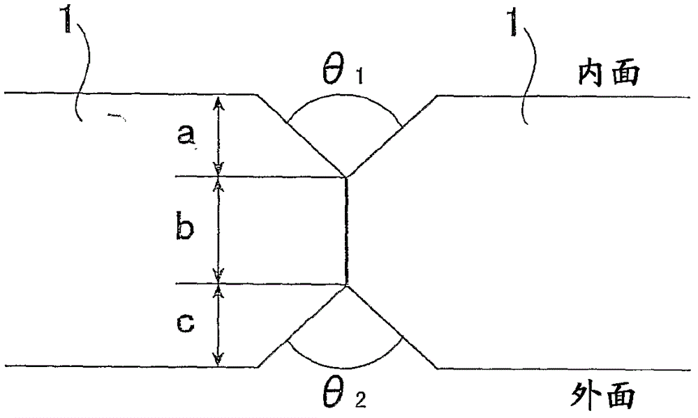
[0066] The steel plate 1 for UOE steel pipes having the chemical composition (chemical composition) shown in Table 1 with a plate thickness of 28, 33, and 38.1 mm was implemented. figure 1 Groove machining (groove machining) of the groove shape shown in Table 3 was performed, and then multi-electrode submerged arc welding of inner and outer single-layer welding was performed under the welding conditions shown in Table 3 to produce welded joints. It should be noted that the groove dimensions are shown in Table 2.
[0067] Collect a Charpy impact test piece (No. 4 test piece specified in JISZ3111) from the produced joint, and perform a Charpy impact test (notch position: FL, test temperature: -30°C) based on the metal material impact test method of JISZ2242, and find Absorbed energy (average of 3 roots).
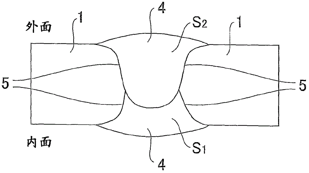
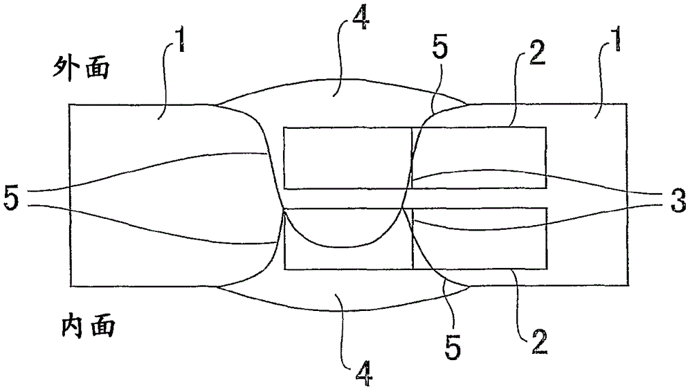
[0068] image 3 The collection position of the Charpy impact test piece 2 is shown. The FL5 of the welded part 4 is taken as the notch position, and the notch 3 is parallel...
Embodiment 2
[0074] according to figure 1 For the groove shape shown, the steel plate having the plate thickness and composition shown in Table 1 of Example 1 is subjected to groove processing with the groove size shown in Table 2 of Example 1, and then welded in the manner shown in Table 5. Conditions Carry out 4-electrode submerged arc welding of inner and outer single-layer welding to make welded joints.
[0075]From the produced joint, Charpy impact test pieces (No. 4 specified in JIS Z3111) were collected in the same manner as in Example 1 so that the position 7 mm below the surface of the steel plate on the side of the steel plate 1 welded on the inner surface or the outer welded side was the center of the Charpy test piece. Test piece) was subjected to a Charpy impact test (notch position: FL, test temperature: -30°C, test number: 3) based on the metal material impact test method of JISZ2242, and the absorbed energy (average value) was obtained. In addition, the notch position 3: F...
PUM
 Abstract
Description
Claims
Application Information
 - R&D Engineer
- R&D Manager
- IP Professional
- Industry Leading Data Capabilities
- Powerful AI technology
- Patent DNA Extraction
Browse by: Latest US Patents, China's latest patents, Technical Efficacy Thesaurus, Application Domain, Technology Topic, Popular Technical Reports.
© 2024 PatSnap. All rights reserved.Legal|Privacy policy|Modern Slavery Act Transparency Statement|Sitemap|About US| Contact US: help@patsnap.com