Fiber pretreatment device and method

A pretreatment device and fiber technology, applied in fiber treatment, textile material treatment, spray/jet textile material treatment, etc., can solve the problems of uniform humidification of fibers, high labor intensity, artificial intermittent, etc., and achieve the goal of overcoming Humidification can not produce continuously, reduce labor intensity and improve production efficiency

Inactive Publication Date: 2012-05-16
上海第三十六棉纺针织服装厂有限公司
View PDF12 Cites 27 Cited by
  • Summary
  • Abstract
  • Description
  • Claims
  • Application Information

AI Technical Summary

Problems solved by technology

[0007] Whether it is wool spinning pretreatment process or cotton spinning pretreatment process, this manual pretreatment method has great defects: labor-intensive, labor-intensive and time-consuming, low efficiency, and the quality is easily affected by human factors. Intermittent
[0008] (2) In the prior art, the effect of mechanical humidification pretreatment is not ideal
The humidification pretreatment method of adding water spray holes to the inner side of the pipeline solves the labor intensity of manual processing and the influence of human factors, but because one or two water spray holes are installed on the inner side of the pipeline, the solution is only sprayed around the circumferential wall of the pipeline. Fiber, it is not easy to spray the fiber in the middle of the cotton pipeline, and it still cannot completely solve the defect of uniform humidification of the fiber
In the drawing process, the water spray head is installed above the sliver at the front roller outlet, and water or chemicals are sprayed on the surface of the sliver, and it is difficult to evenly humidify the fibers.
[0011] Whether it is in wool spinning or cotton spinning, if the spinnability is relatively poor, the fibers that need to be treated with additives are not evenly humidified. It is easy to adhere to the surface of equipment such as top rollers, affecting equipment operation and product quality
The over-wet fiber is easy to wrap around the carding element during subsequent processing, or cannot be drafted to form a "hard head", which also affects the normal operation of production and yarn quality

Method used


Image

  • Fiber pretreatment device and method
  • Fiber pretreatment device and method
  • Fiber pretreatment device and method

Examples


Embodiment 1

[0059] Fiber pretreatment device:

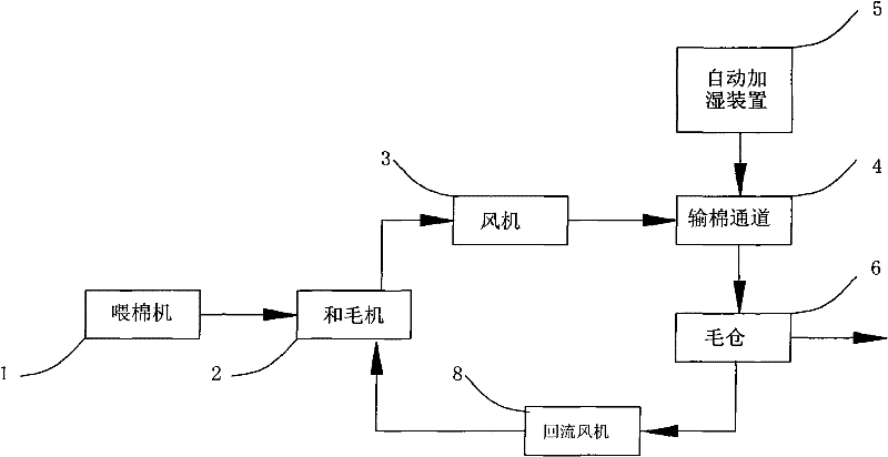
[0060] like figure 1 As shown, a fiber pretreatment device is composed of a cotton feeding machine 1, a knitting machine 2, a fan 3, a cotton transport channel 4, an automatic humidifying device 5 and a wool bin 6.

[0061] The cotton feeding machine 1 is connected with the cotton wool machine 2, and the wool machine 2 is connected with the fan 3. The fan 3 is connected to the top of the wool bin 6 through the cotton delivery pipeline 4, and the automatic humidifying device 5 is connected with the cotton delivery pipeline 4, and enters the top of the wool warehouse 6. .

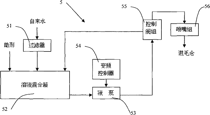
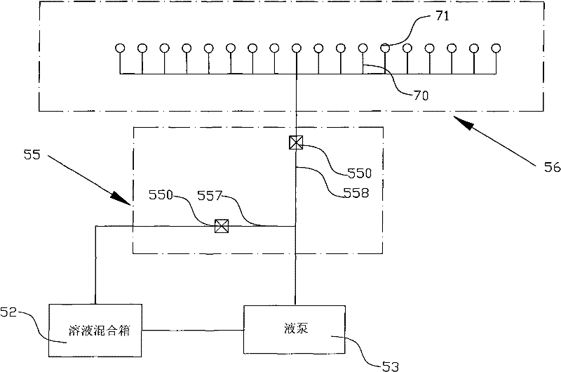
[0062] like figure 2 As shown, the automatic humidifying device 5 is composed of a filter 51, a solution mixing tank 52, a liquid pump 53, a control valve group 55 and a nozzle group 56. The filter 51, the solution mixing tank 52, the liquid pump 53 and the control valve group 55 pass through the pipeline Connection, the control valve group 55 is connected with the nozz...

Embodiment 2

[0096] Fiber pretreatment device:

[0097] like figure 1 As shown, a fiber pretreatment device is composed of a cotton feeding machine 1, a knitting machine 2, a fan 3, a cotton transport channel 4, an automatic humidifying device 5 and a wool bin 6.

[0098] Cotton feeding machine 1 is connected with woolen machine 2, and woolen machine 2 is connected with fan 3 again, and fan 3 is connected wool warehouse 6 tops through cotton conveying pipeline 4, and automatic humidifying device 5 and cotton conveying pipeline 4 enter wool warehouse 6 tops.

[0099] like figure 2 As shown, the automatic humidifying device 5 is composed of a filter 51, a solution mixing tank 52, a liquid pump 53, a control valve group 55 and a nozzle group 56. The filter 51, the solution mixing tank 52, the liquid pump 53 and the control valve group 55 pass through the pipeline Connection, the control valve group 55 is connected with the nozzle group 56 pipelines, and the control valve group 55 is connec...

Embodiment 3

[0112] Fiber pretreatment device:

[0113] Such as figure 1 As shown, a fiber pretreatment device is composed of a cotton feeding machine 1, a knitting machine 2, a fan 3, a cotton transport channel 4, an automatic humidifying device 5 and a wool bin 6.

[0114] Cotton feeding machine 1 is connected with woolen machine 2, and woolen machine 2 is connected with fan 3 again, and fan 3 is connected wool warehouse 6 tops through cotton conveying pipeline 4, and automatic humidifying device 5 and cotton conveying pipeline 4 enter wool warehouse 6 tops.

[0115] Such as figure 2 As shown, the automatic humidifying device 5 is composed of a filter 51, a solution mixing tank 52, a liquid pump 53, a control valve group 55 and a nozzle group 56. The filter 51, the solution mixing tank 52, the liquid pump 53 and the control valve group 55 pass through the pipeline Connection, the control valve group 55 is connected with the nozzle group 56 pipelines, and the control valve group 55 is ...


PUM

PropertyMeasurementUnit
heightaaaaaaaaaa

Abstract

The invention discloses a fiber pretreatment device and method. The fiber pretreatment device comprises a cotton feeder, a wool mixer, a fan, a cotton conveying channel, an automatic humidification device and a wool bin which are connected in sequence by pipes; the automatic humidification device is connected with the cotton conveying channel; the fiber pretreatment device further comprises a reflow fan; the reflow fan is connected with the wool mixer and the wool bin through pipes; the wool bin is provided with an air blowing device; and the air blowing device is a ventilating pipe which is connected with an air blower. The method for humidifying manually for fiber pretreatment for a long time is changed, the working labor intensity is reduced, the defect of incontinuous production caused by manual humidification is overcome, and the reflow step, namely the secondary humidification step is adopted so that the fiber pretreatment can further meet the yarn spinning requirement and the fiber spinnability is improved.

Description

technical field [0001] The invention relates to a fiber pretreatment device and a fiber pretreatment method. Background technique [0002] With the development of textile science and technology, the field of natural fibers that can be spun and processed yarns has been further expanded, and new man-made fibers have emerged in an endless stream. The yarn has been developed from pure spinning of single fiber or blending of two fibers to multi-fiber blended yarn of more than three fibers. The fibers used range from ordinary fibers such as cotton, wool, polyester to milk fibers, temperature-adjusting fibers, New generation fibers such as sulfone fiber. The characteristics of these fibers are different, the spinnability is also different, and the characteristics of the fibers in the spinning process are also different. Some fibers have good spinnability and can be processed according to conventional spinning methods. Some fibers, especially wool , milk fiber, sulfonamide fiber, ...

Claims


Application Information

Patent Timeline
Patent Type & Authority Applications(China)
IPC IPC(8): D01G21/00D06B1/02D06B15/12
Inventor 阎均王伟君钱春芳冯宝龙
Owner 上海第三十六棉纺针织服装厂有限公司
Why Eureka
Try Eureka