Low-noise and large-power hydraulic plunger pump

A hydraulic plunger pump, high-power technology, applied in the field of hydraulic plunger pumps, can solve the problems of poor adaptability and poor adaptability, and achieve the effects of good sealing performance, increased rated working pressure, and low noise

Inactive Publication Date: 2012-05-16
夏成法
View PDF0 Cites 6 Cited by
  • Summary
  • Abstract
  • Description
  • Claims
  • Application Information

AI Technical Summary

Problems solved by technology

Existing methods to solve the noise caused by pressure pulsation: 1. Preloading and decompression type distribution plate: By setting a cover angle on the distribution plate, the cylinder hole will not be connected to the oil discharge chamber immediately after leaving the oil suction chamber, but will be turned over The stroke is compressed at a certain angle, so that the pressure in the cylinder hole rises to the oil discharge pressure, and then connects with the oil discharge chamber, so as to avoid pressure shock; its characteristics are: 1. For pumps with low rated pressure and small cylinder bore dead volume , has good practicability under rated working conditions; 2. It has good effect on pumps with constant working conditions such as constant pressure and fixed quantity, but poor adaptability to variable pressure and variable pumps
2. Throttle hole type distribution plate: a throttle hole is set on the distribution plate, the bottom of the throttle hole is connected with the oil discharge chamber (or oil suction chamber), the plunger moves in the cylinder hole, and passes through the throttle hole to the cylinder. The pre-boost (or pre-decompression) effect produced by part of the liquid injected into (or released from the cylinder bore) to eliminate the sudden pressure change in the cylinder bore; its characteristics are: 1. It has a certain adaptability when the working condition deviates from the rated working condition; 2. When the working condition deviates too much from the rated working condition, the adaptability is not good

Method used


Image

  • Low-noise and large-power hydraulic plunger pump
  • Low-noise and large-power hydraulic plunger pump

Examples


Embodiment Construction

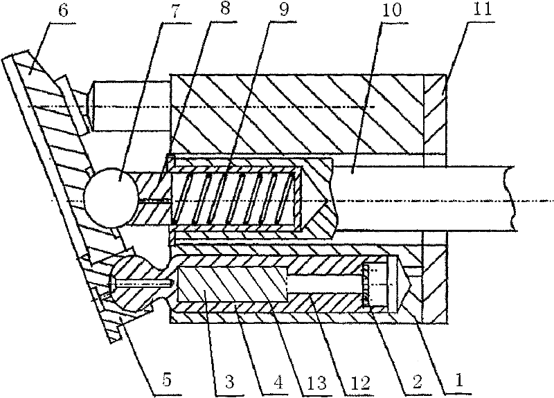
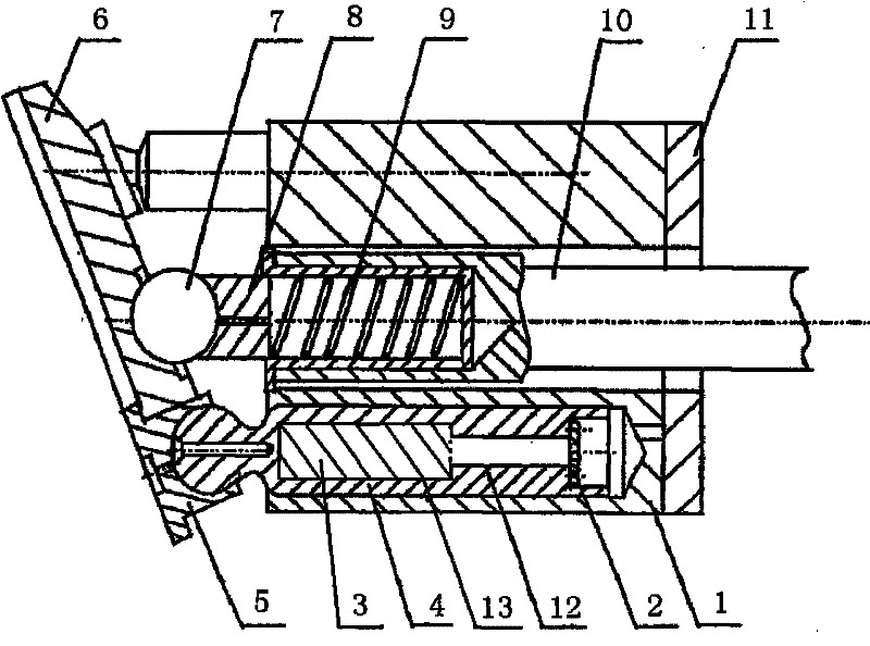
[0010] See eg figure 1 , a low-noise high-power hydraulic plunger pump, including a cylinder 1, a flange 2, an accumulator 3, a plunger 4, a shoe 5, a pressure plate 6, a steel ball 7, an inner sleeve 8, a spring 9, and a main shaft 10. Distributing plate 11, the end surface of the inner cavity of the plunger close to the end of the distributing plate is equipped with a flange 2 with several small through holes in the axial direction, and the inner cavity of the plunger 4 facing the side of the distribution device is A small cavity 12, towards the blind end is a large cavity 13, the accumulator 3 is arranged in the large cavity 13 of the inner cavity of the plunger 4, and the accumulator is connected with the internal cavity of the plunger 4 The large cavity 13 of the cavity is of the same shape as an infused elastic material or a viscoelastic damping material. The accumulator is arranged in the large cavity of the inner cavity of the plunger. The inner cavity of the plunger ...


PUM


Abstract

The invention discloses a low-noise and large-power hydraulic plunger pump. The low-noise and large-power hydraulic plunger pump comprises a cylinder, a flange, an accumulator, a plunger, piston shoes, a pressure plate, a steel ball, an inner sleeve, a spring, a main shaft, and a valve plate; the accumulator is arranged in an inner hole cavity of the plunger; the end face, near the end of the valve plate, of the inner hole cavity of the plunger is provided with a flange in which a plurality of small through holes are formed in the axial direction; one side, facing the valve plate, of the inner hole cavity of the plunger is provided with a small hole cavity, and the side, facing a blind end, of the inner hole cavity of the plunger is provided with a large hole cavity; and the accumulator is arranged in the large hole cavity of the inner hole cavity of the plunger. The hydraulic plunger pump has good sealing performance, low noise and high rated operating pressure.

Description

technical field [0001] The invention relates to a hydraulic plunger pump, in particular to a low-noise, high-power hydraulic plunger pump with an accumulator. Background technique [0002] The fluid noise of the plunger pump is mainly generated by the flow distribution process. During the flow distribution process, when the plunger cavity transitions from the oil suction area to the oil discharge area, the plunger cavity filled with low-pressure oil suddenly connects with the high-pressure oil in the oil discharge area, causing high-pressure oil to enter the plunger cavity from the oil discharge area, forming Flow backflow impact. With the increase of the pressure of the plunger and the backflow flow, the pressure in the plunger chamber rises to be equal to the pressure of the oil discharge area. As the plunger continues to be pressed in, the plunger chamber enters the oil discharge working condition. However, due to the inertia and damping effect of the oil, the discharge...

Claims


Application Information

Patent Timeline
Patent Type & Authority Applications(China)
IPC IPC(8): F04B1/16
Inventor 夏成法
Owner 夏成法
Why Eureka
Try Eureka