
Radar antenna power failure detection circuit

A technology of power failure and detection circuit, applied in the direction of power supply testing, etc., which can solve the problems of huge power system, complicated power failure detection, abnormal operation of T/R components, etc.

Inactive Publication Date: 2012-05-16
徐鑫
View PDF0 Cites 8 Cited by
  • Summary
  • Abstract
  • Description
  • Claims
  • Application Information

AI Technical Summary

Problems solved by technology

[0002] With the widespread use of phased array antennas in radar, the fault detection of antenna power supply becomes more and more important. The power supply scale of phased array antennas is often proportional to the number of transceiver (T / R) components. When T / R When there are hundreds of components, the power system is relatively large, and the detection of power failure is also complicated. Power failure will directly lead to abnormal operation of T / R components

Method used


Image

  • Radar antenna power failure detection circuit
  • Radar antenna power failure detection circuit

Examples


Embodiment Construction

[0008] The invention includes a signal conditioning circuit, a multiplexing circuit, an analog-to-digital conversion circuit, a single-chip microcomputer, a peripheral circuit, and a CPLD logic circuit. The multiplexer chooses to enter the analog-to-digital converter and converts it into a digital quantity. The single-chip microcomputer reads the digital quantity and compares it with the specified upper and lower limits to determine whether the voltage is correct. Finally, a unit-level fault table is generated and transmitted through the RS-485 interface. to the superior for processing.

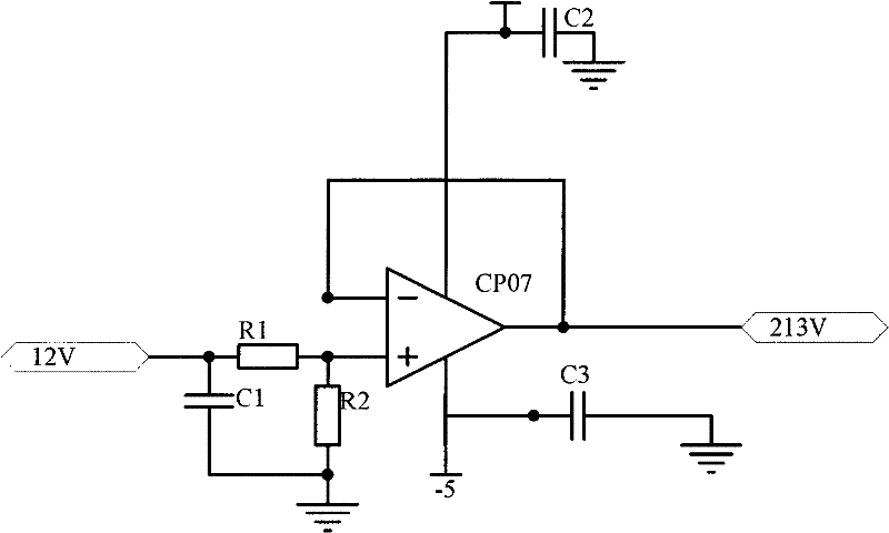
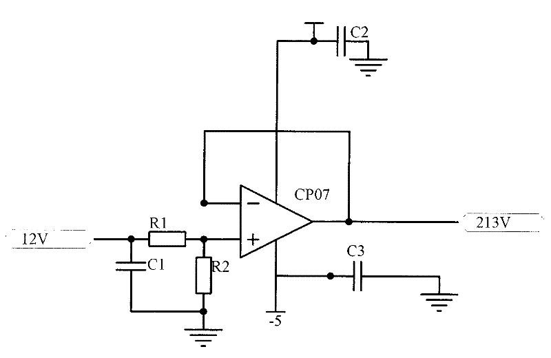
[0009] Capacitor C1 filters out high-frequency glitches, and precision resistors R1 and R2 form a voltage divider circuit; MUX circuit consists of two stages, and the front stage consists of five multiplexers selected from eight. After conditioning, it is connected to these MUXs. The rear stage is composed of a multiplexer, which further selects the five-way voltage output by the front stage....


PUM


Abstract

The invention provides a radar antenna power failure detection circuit. The invention relates to a failure detection circuit, in particular to the radar antenna power failure detection circuit which is capable of monitoring a power supply in real time and finding the failure in time. The radar antenna power failure detection circuit comprises a signal conditioning circuit, a multiplexing circuit, an analog-to-digital conversion circuit, a singlechip microcomputer and a peripheral circuit thereof as well as a complex programmable logic device (CPLD) logic circuit, and has the structural key points that the signal conditioning circuit is used for carrying out filtering, voltage distribution and impedance matching on 35 ways of power detection signals which are input into the signal conditioning circuit; then, the power detection signals are selected by multiplexers and enter into the analog-to-digital conversion circuit so as to be converted into digital quantity; the digital quantity is read in by the singlechip microcomputer; then compared with the specified upper and lower bound, whether the voltage is correct or not can be judged; and finally, a cell-level fault list is generated and transmitted to the higher authority through a remote sensing (RS)-485 interface to be processed.

Description

Technical field: [0001] The invention relates to a fault detection circuit, in particular to a radar antenna power supply fault detection circuit. Background technique: [0002] With the widespread use of phased array antennas in radar, the fault detection of the antenna power supply becomes more and more important. The power supply scale of the phased array antenna is often proportional to the number of transceiver (T / R) components. When there are hundreds of components, the power supply system is relatively large, and the detection of power failures is also complicated. Power failures will directly lead to abnormal operation of the T / R components. Invention content: [0003] In view of the above problems, the present invention provides a radar antenna power supply fault detection circuit that monitors the power supply in real time and finds faults in time. [0004] In order to achieve the above purpose, the present invention adopts the following technical solutions. The...

Claims


Application Information

Patent Timeline
Patent Type & Authority Applications(China)
IPC IPC(8): G01R31/40
Inventor 徐鑫
Owner 徐鑫
Learn More