
Pressure control method and device of transmission cavity as well as plasma equipment

A transmission chamber and pressure technology, which is applied in the direction of electric fluid pressure control, semiconductor/solid-state device manufacturing, electrical components, etc., can solve the problems of high cost of pressure control equipment, incapability of real-time and dynamic control of the air pressure in the transmission chamber, etc. Achieve the effect of saving equipment cost, shortening the time of pressure adjustment, and ensuring real-time performance

Active Publication Date: 2013-07-17
BEIJING NAURA MICROELECTRONICS EQUIP CO LTD
View PDF3 Cites 0 Cited by
  • Summary
  • Abstract
  • Description
  • Claims
  • Application Information

AI Technical Summary

Problems solved by technology

[0006] The invention provides a pressure control method, device and system of a transmission chamber, which is used to solve the technical problem that the cost of pressure control equipment in the prior art is high and the air pressure in the transmission chamber cannot be controlled in real time and dynamically

Method used


Image

  • Pressure control method and device of transmission cavity as well as plasma equipment
  • Pressure control method and device of transmission cavity as well as plasma equipment
  • Pressure control method and device of transmission cavity as well as plasma equipment

Examples


Embodiment 2

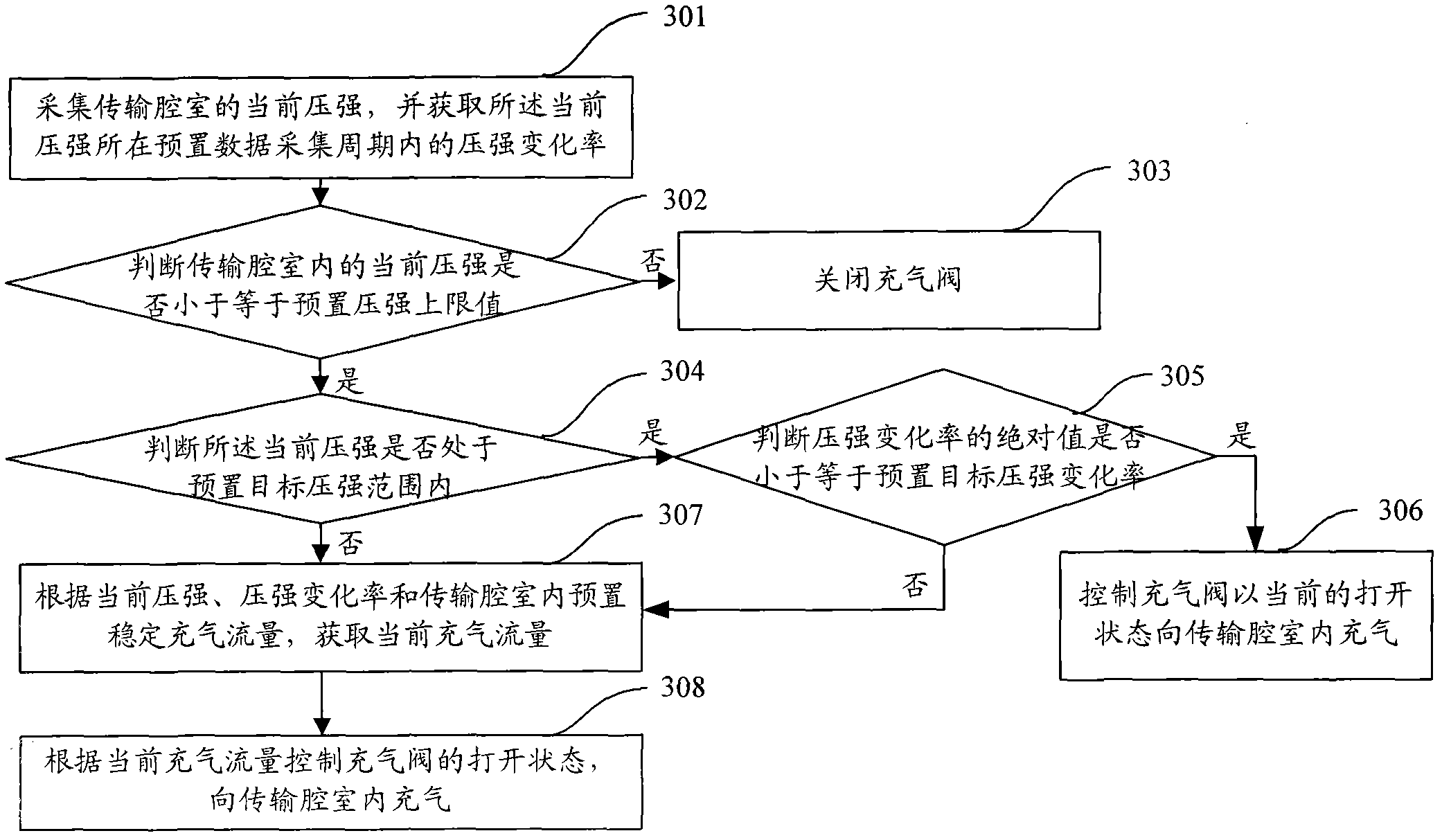
[0083] Step 308 in the second embodiment is the same as step 103 in the first embodiment, and will not be repeated here. After step 308 is executed, it is necessary to return to step 301 and execute the above steps in a loop until the end of the pressure control process.

[0084] Compared with Embodiment 1, Embodiment 2 of the present invention, when the current pressure in the transmission chamber is higher than the preset threshold value, by completely closing the inflation valve, the pressure in the transmission chamber can be reduced rapidly, shortening the time for pressure adjustment, and improving the controllability. pressure efficiency. When the current pressure is within the preset target pressure range, and the absolute value of the pressure change rate within the preset data collection period is less than or equal to the preset target pressure change rate, the second embodiment of the present invention does not recalculate and modify the inflation flow rate to prev...


PUM


Abstract

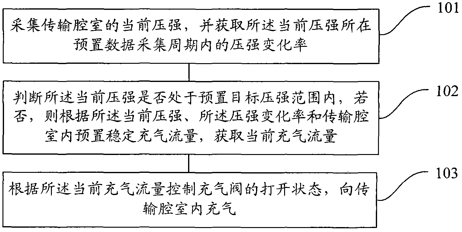
The invention provides a pressure control method and device of a transmission cavity as well as plasma equipment. The pressure control method comprises the following steps of: collecting the current pressure of the transmission cavity and obtaining the pressure change rate of the current pressure within a pre-set data collection period; judging whether the current pressure is within a pre-set target pressure range; if not, obtaining the current aeration flow according to the current pressure, the pressure change rate and a pre-set stable aeration flow in the transmission cavity; and controlling the opening status of an inflation valve according to the current aeration flow to inflate the transmission cavity. According to the invention, the air pressure in the transmission cavity can be dynamically adjusted in real time and the equipment cost is saved.

Description

technical field [0001] The invention relates to semiconductor process control technology, in particular to a pressure control method, device and plasma equipment of a transmission chamber. Background technique [0002] In semiconductor processing technology, silicon wafers are generally processed by etching equipment. The transfer chamber (TC, Transfer Chamber) of the etching machine equipment is a very important part of the entire etching equipment. The only way to transmit between. In an ideal working state, the transfer chamber needs to maintain a vacuum state, so the air pressure in the transfer chamber is very low, but after the silicon wafer is processed in the reaction transfer chamber, polluting gas particles will be produced; when the transfer When the chamber and the reaction chamber are connected, if the pressure in the transfer chamber is lower than the pressure in the reaction, the contamination particles generated in the reaction transfer chamber will enter t...

Claims


Application Information

Patent Timeline
Patent Type & Authority Patents(China)
IPC IPC(8): G05D16/20H01L21/00
Inventor 李虎
Owner BEIJING NAURA MICROELECTRONICS EQUIP CO LTD
Learn More