Impact wrench

一种冲击扳手、主轴的技术,应用在冲击扳手领域,能够解决减弱锤子旋转冲击力、阻碍主锤顺畅移动、未设置保持副锤旋转轴线等问题,达到增大惯性矩、强旋转冲击力的效果

Active Publication Date: 2012-05-16
KUKEN CO LTD
View PDF8 Cites 17 Cited by
  • Summary
  • Abstract
  • Description
  • Claims
  • Application Information

AI Technical Summary

Problems solved by technology

[0015] Second, there is no mechanism to maintain the axis of rotation of the secondary hammer
The generation of swing rotation of the core hinders the smooth movement of the main hammer in the axial direction and becomes the cause of weakening the rotational impact force generated by the hammer

Method used


Image

  • Impact wrench
  • Impact wrench
  • Impact wrench

Examples


no. 1 approach

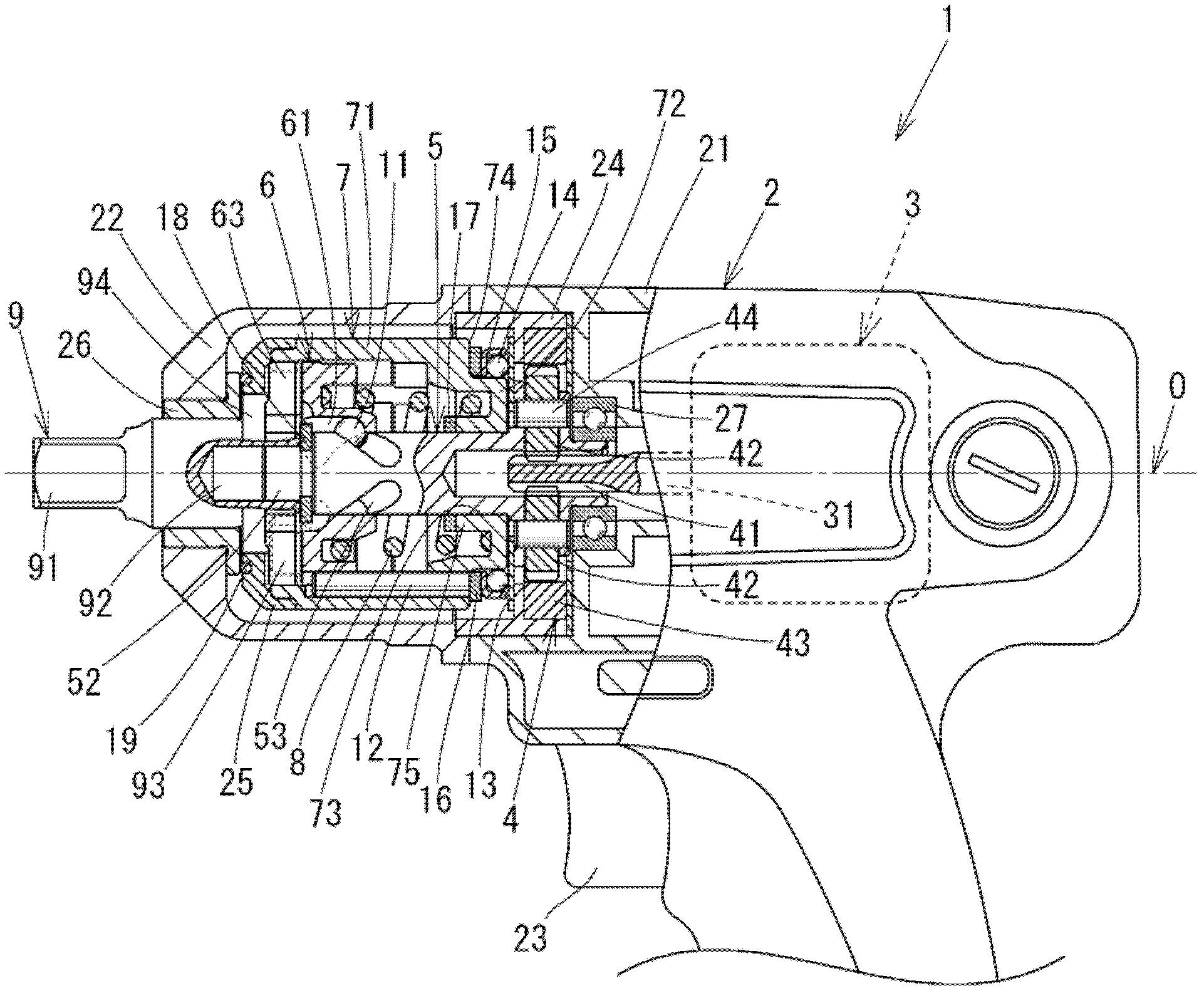
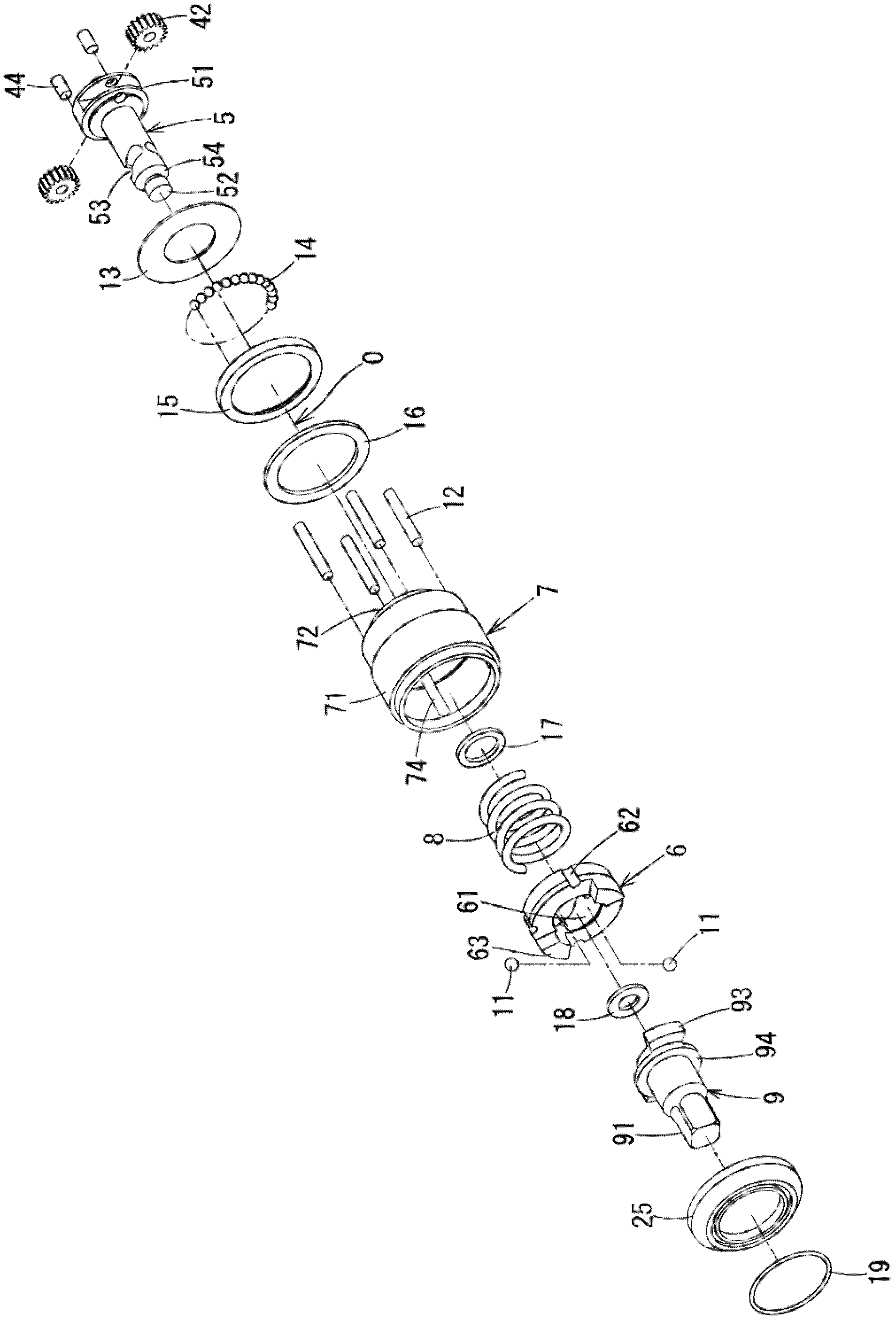
[0070] figure 1 It is a main part front view of the main part of the impact wrench according to the first embodiment of the present invention cut along the longitudinal plane including the axis of the main shaft. figure 2 is to express figure 1 Perspective view of the components of the impact wrench except the housing part.

[0071]

[0072] The impact wrench 1 includes: a housing 2 , an electric motor 3 , a rotation transmission mechanism 4 , a main shaft 5 , a main hammer 6 , an auxiliary hammer 7 , a spring 8 , and a mounting seat 9 . Hereinafter, the configuration and function of the above-mentioned components will be described respectively.

[0073] First, the casing 2 will be described. The housing 2 is composed of a resin housing 21 disposed at the rear of the impact wrench 1 and an aluminum clutch housing 22 disposed at the front, and the clutch housing 22 is fixed to the housing 21 with screws (not shown). Hereinafter, the side where the mounting base 9 is arra...

no. 2 approach

[0133] Figure 5 It is a main part front view of the main part of the impact wrench according to the second embodiment of the present invention cut along the longitudinal plane including the axis of the main shaft. The impact wrench 1a of the second embodiment is different from the impact wrench 1 of the first embodiment in that the structure of a core holding mechanism that holds the rotation axis of the sub hammer in a state aligned with the axis of the main shaft is different. Correspondingly, the main shaft 5, auxiliary hammer 7, and mounting seat 9 of the first embodiment are replaced with the main shaft 5a, auxiliary hammer 7a, and mounting seat 9a.

[0134] Hereinafter, the structure and operation of the impact wrench 1a will be described, focusing on the structure of the core holding mechanism. In addition, in Figure 5 in, with figure 1 Components having the same functions as the impact wrench 1 are denoted by the same reference numerals, and description thereof wi...

no. 3 approach

[0147] In the first and second embodiments, the impact wrench 1 using the mounts 9 and 9a for tightening bolts and nuts has been described, but by using the mount with a hole at the tip , It can also be used as an impact wrench for tightening small screws with notches or cross recesses, etc., and a hexagonal drill bit as a screwdriver bit (DRAIBA BITSTO) is inserted into the above-mentioned hole. Image 6 It shows the cross section of the front part of the impact wrench 1b according to the third embodiment of the present invention, and the impact wrench 1b is replaced by a mount 9b formed with a hole for inserting a hexagonal bit. figure 1 Mounting seat 9 for impact wrench 1 shown.

[0148] A drill insertion hole 95 for detachably attaching a hexagonal drill is formed along the axis O at the front portion of the mount 9b. In addition, a steel ball 97 engaged with a groove provided in the hexagonal bit is inserted into a hole 96 formed in the outer peripheral surface of the mo...


PUM


Abstract

An impact wrench is provided that can mitigate vibrations in the axial direction without reducing the rotary impact force of hammers. The hammers are composed of a primary hammer (6) fitted to the outer circumference of a spindle (5) and a cylindrical secondary hammer (7) that is disposed so as to cover the primary hammer (6) and that rotates together with the primary hammer (6). Furthermore, the secondary hammer (7) is held by a axis holding means in a state in which the rotational axis of the secondary hammer (7) is coincident with the axis of the spindle (5) in order to prevent precession movement. With the use of the hammer configuration of the present invention, the mass of the primary hammer (6) can be decreased compared to that of the secondary hammer (7), and therefore it is possible to mitigate vibrations in the axial direction while maintaining the rotary impact force.

Description

technical field [0001] The present invention relates to an impact wrench that securely tightens a bolt or a nut by applying an impact in a rotational direction. Background technique [0002] The impact wrench tightens bolts or nuts by applying the impact force generated by a hammer that is driven to rotate to a mounting seat that is an output shaft. An impact wrench has a motor, a spindle, a hammer, and a mount as its main components. Hereinafter, its operation will be briefly described. [0003] The motor rotates the main shaft at a predetermined rotational speed, and transmits the rotational force of the main shaft to the hammer. By the rotation of the hammer, the claw provided on the hammer collides with the engaging claw provided on the mount. Next, by utilizing this impact, a predetermined torque is applied to the sleeve body attached to the front end of the mount, thereby tightening the bolt or nut. [0004] The aforementioned impact wrenches are classified into var...

Claims


Application Information

Patent Timeline
Patent Type & Authority Applications(China)
IPC IPC(8): B25B21/02
CPCB25B21/00B25B21/026
Inventor 中村晃规
Owner KUKEN CO LTD
Why Eureka
Try Eureka