Rotary ultrasonic imaging system

An imaging system, rotating ultrasound technology, applied in ultrasonic/sonic/infrasonic diagnosis, sonic diagnosis, infrasonic diagnosis, etc., can solve the problems of acoustic mismatch, ultrasonic transducer degradation, signal attenuation, etc., achieve simple structure, improve lateral Resolution and performance, easy-to-manufacture effects

Active Publication Date: 2012-05-23
THE HONG KONG POLYTECHNIC UNIV
View PDF6 Cites 9 Cited by
  • Summary
  • Abstract
  • Description
  • Claims
  • Application Information

AI Technical Summary

Problems solved by technology

[0004] The technical problem to be solved by the present invention is: the rotating ultrasonic imaging system of the prior art achieves the focusing effect by adding an extra lens, which may cause signal attenuation and acoustic mismatch; the hard-pressed piezoelectric vibrator will cause the ultrasonic transducer Degradation and shorting; and the need for a large number of components, especially for the electrical signal output of the 360-degree rotating ultrasonic transducer

Method used


Image

  • Rotary ultrasonic imaging system
  • Rotary ultrasonic imaging system
  • Rotary ultrasonic imaging system

Examples


Embodiment Construction

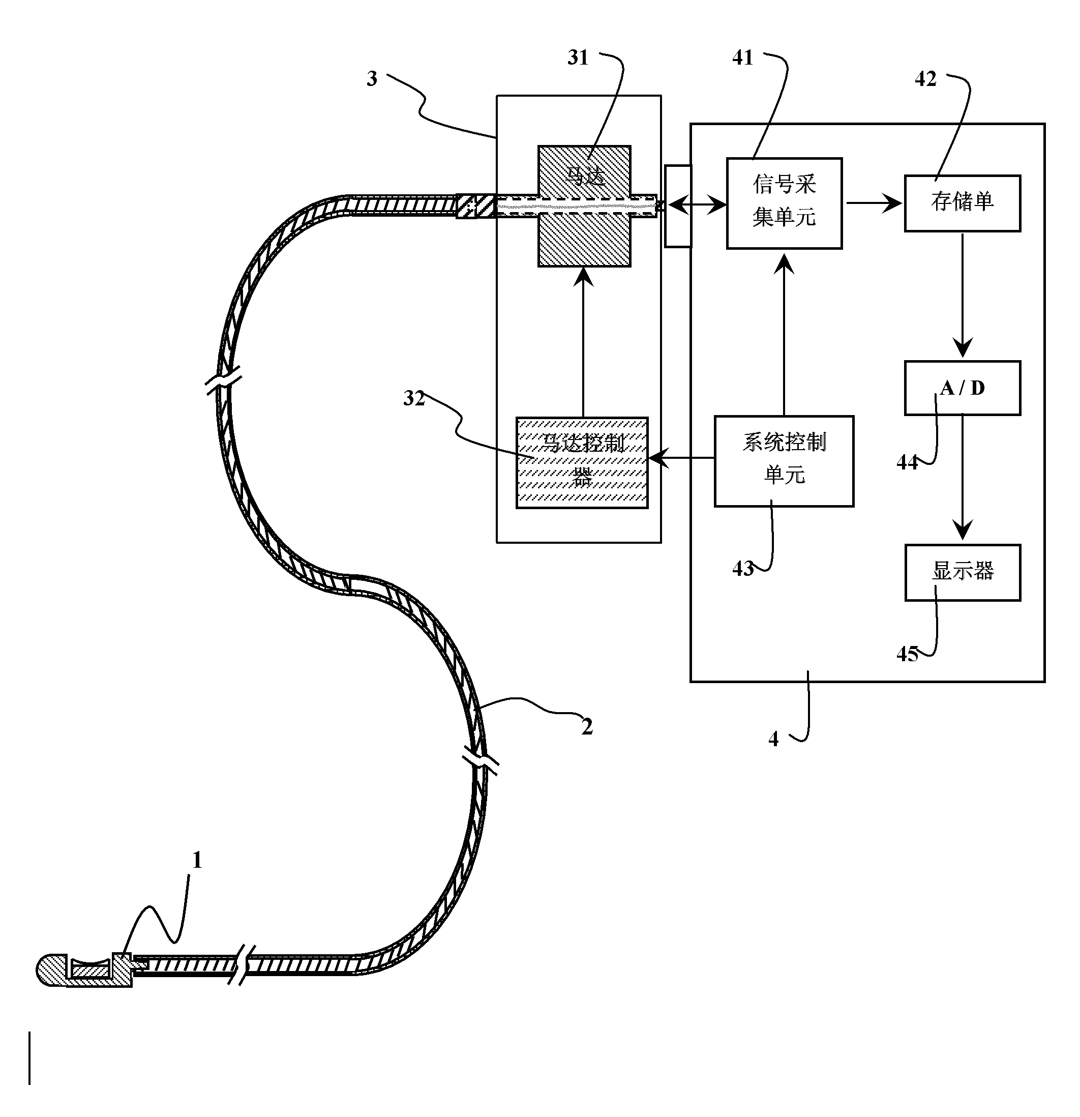
[0025] Such as figure 1 As shown, the rotating ultrasonic imaging system of the present invention mainly includes three parts: the control device 4 , the ultrasonic probe 1 and the rotating motor device 3 . Wherein, the ultrasonic probe 1 is used as the inspection part of the signal, and the ultrasonic probe 1 can be introduced into the body or arteries to image organs or tissues in the body (such as lung, liver, inner wall of blood vessels, etc.), so as to output ultrasonic detection signals. The rotary motor device 3 is connected to the ultrasonic probe 1 through a flexible connector 2. In addition to realizing the mechanical connection between the rotary motor device 3 and the flexible connector 2, the flexible connector 2 is also used to send the ultrasonic detection signal output by the ultrasonic probe 1 to control unit 3. During the process of transmitting the ultrasonic detection signal from the flexible connector 2 to the control device 3 , the rotating motor device ...


PUM


Abstract

The invention relates to a rotary ultrasonic imaging system, which comprises a control device, an ultrasonic probe and a rotary motor device. The rotary motor device receives ultrasonic signals sent by the ultrasonic probe and outputs the ultrasonic signals to the control device through 360-degree rotation; the ultrasonic probe includes housing with a mounting groove; and the mounting groove is internally provided with an ultrasonic energy converter having a focusing concave surface. By directly forming the focusing concave surface on the ultrasonic energy converter, the focusing of the rotary ultrasonic imaging system is realized without adding extra components (such as lenses), and transverse resolution as well as performance are improved; and by forming a rotary motor output shaft of the rotary ultrasonic imaging system into a hollow shaft to provide a 360-degree rotary path for the transmission of the ultrasonic signals from the ultrasonic energy converter to the control device, position calibration of the 360-degree rotary ultrasonic energy converter and leading-out of electric signals can be solved without designing a complex module. Such design can efficiently shield electric noise interference.

Description

technical field [0001] The present invention relates to a rotating ultrasonic imaging system, and more particularly, to a rotating ultrasonic imaging system. Background technique [0002] Due to the inherent nature of conventional planar ultrasound transducers, the resulting image quality is severely limited in terms of lateral resolution and acoustic intensity, especially in high-resolution imaging applications. Focused ultrasound transducers are therefore used to improve lateral resolution and performance. Common methods to prepare focused ultrasound transducers are to change the shape of piezoelectric vibrators or to use lenses. It has been reported that the addition of external lenses can cause signal attenuation and acoustic mismatch, therefore, transducers that change the shape of the vibrator are more advantageous in highly sensitive devices. Piezoelectric vibrators are usually formed using hard pressing and pressure deflection techniques. Due to the softness of po...

Claims


Application Information

Patent Timeline
Patent Type & Authority Applications(China)
IPC IPC(8): A61B8/12
CPCA61B8/4461A61B8/445A61B8/12
Inventor 林国豪陈燕戴吉岩陈王丽华
Owner THE HONG KONG POLYTECHNIC UNIV
Why Eureka
Try Eureka