Catalytic cracking method and device

A catalytic cracking device and catalytic cracking technology, applied in the field of petrochemical industry, can solve the problems affecting the regeneration process, the large amount of transport medium, and the effect of stripping, so as to achieve the goals of reduced investment, simple engineering implementation, and reduced unfavorable secondary reactions Effect

Inactive Publication Date: 2012-05-23
石宝珍
View PDF7 Cites 3 Cited by
  • Summary
  • Abstract
  • Description
  • Claims
  • Application Information

AI Technical Summary

Problems solved by technology

However, in this technology, the catalyst separated from the first zone must be stripped before entering the regenerator. At the same time, the regenerated catalyst must be transported by the conveying medium before entering the second stage. The stripping steam and conveying medium will all enter the second stage, which will inevitably affect The reaction to the second stage; if the amount of stripping steam is limited, the stripping effect will be affected, and then the regeneration process will be affected; the height difference from the bottom of the external heat extractor to the entrance of the second reaction stage is tens of meters, and the amount of transport medium is large , need to consume a lot of energy; and this technology requires two settlers, two stripping sections, a substantial increase in investment

Method used


Image

  • Catalytic cracking method and device
  • Catalytic cracking method and device
  • Catalytic cracking method and device

Examples


Embodiment 1

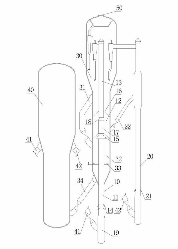
[0042] The design of a catalytic cracking unit in an oil refinery is as follows: figure 1 As shown, the heavy oil at 220°C is atomized through the nozzle 14, enters the first reaction zone 11 of the main riser reactor 10, mixes with the regenerated catalyst at about 640°C and gasifies, and flows upward along the first reaction zone 11 , and react continuously, the reaction time is 1.0s, and the reaction temperature is 520°C. After the reaction is completed, the mixture is separated from the catalyst through the splitter 15, and the oil and gas go upward along the delivery pipe 17 and enter the second reaction zone 13; meanwhile, from the auxiliary light raw material riser The spent catalyst drawn from the reactor 20 enters the catalyst replenishment zone 12 and enters the second reaction zone 13, contacts and mixes with the reaction oil and gas entering the second reaction zone 13 and continues to react. The reaction temperature is 510°C and the reaction time is 1.5s. Light g...

Embodiment 2

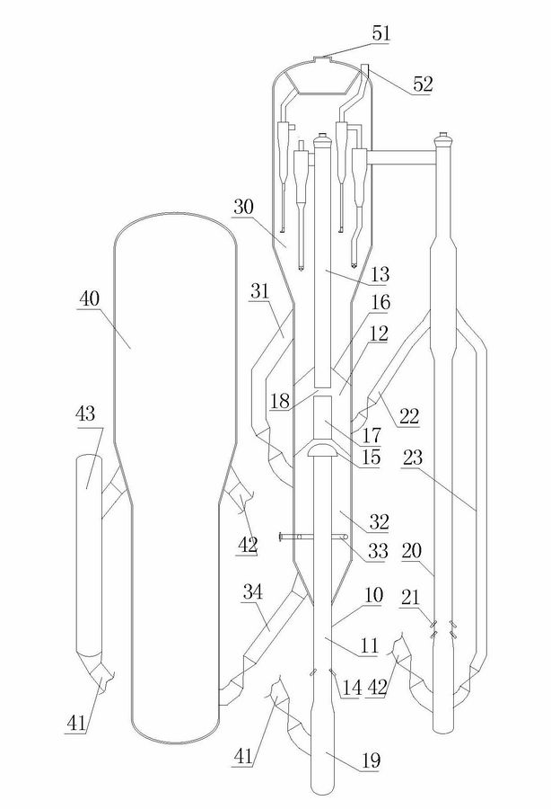
[0045] The design of a catalytic cracking unit in an oil refinery is as follows: figure 2 As shown, a catalyst cooler 43 is provided on the regeneration standpipe 41, and a catalyst return pipe 23 is provided in the auxiliary light raw material riser reactor 20; the reactor 20 shares the settler 30 with the main reactor 10, but does not share the gas-solid separator , the oil and gas in the two reactors are treated separately, and the rest of the device structure is the same figure 1 . In this embodiment, the heavy oil raw material and the regenerated catalyst at about 600° C. are contacted and reacted in the first reaction zone 11; the circulating amount of the ungenerated catalyst returned from the reactor 20 is controlled by the slide valve on the catalyst return pipe 23, and the returned amount is 40%; the reaction raw material of the reactor 20 is mixed C4 components. In this embodiment, the reaction temperature in the first reaction zone of the riser reactor 10 is 50...

Embodiment 3

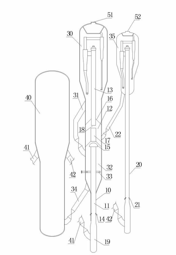
[0047] The design of a catalytic cracking unit in an oil refinery is as follows: image 3 As shown, the second settler 35 is separately set at the outlet of the auxiliary reactor 20; the unborn catalyst of the auxiliary reactor 20 is drawn from the second settler 35, and enters the second reaction zone 13 through the catalyst replenishment zone 12, and the oil and gas in the two reactors Treat them separately. The rest of the device structure is the same as figure 1 . In this embodiment, the reaction raw material of the riser reactor 20 is C4 component, and the reaction conditions of the riser reactor 10 are: the reaction temperature of the first reaction zone is 520° C., and the reaction time is 1.0s; the reaction temperature of the second reaction zone is 510° C. °C, the reaction time is 1.5s; the reaction temperature of the riser reactor 20 is 520 °C, and the reaction time is 2.5s; the total reaction liquid yield increases by about 2%.


PUM


Abstract

The invention discloses a catalytic cracking method and a device for realizing the method, belonging to the technical field of the petrochemical industry. Catalytic cracking is carried out in a main reactor and an auxiliary light raw material reactor, a regenerated catalyst from a regenerator is subjected to contact reaction with a raw oil in a first reaction zone of the main reactor, and a reaction mixture is upwards fed to a flow divider so as to separate out the catalyst; the separated catalyst directly flows into a stripping section, and reaction oil gas is upwards fed into a second reaction zone of the main reactor along a delivery pipe; a spent catalyst from the auxiliary light raw material reactor is firstly fed into a catalyst replenishing zone and then is upwards fed into the second reaction zone of the main reactor from the catalyst replenishing zone so as to be mixed with the reaction oil gas from the first reaction zone and make the oil gas subjected to continuous reaction; and after the reaction is finished, the oil gas and the catalyst are separated, the oil gas is led out and then fed into a subsequent fractionating system through an oil gas outlet pipeline, the catalyst flows into the stripping section and is stripped and fed into the regenerator for regeneration, together with the catalyst separated out by the flow divider in the first reaction zone.

Description

technical field [0001] The invention relates to the field of petrochemical technology, in particular to a method and device for catalytic cracking of petroleum hydrocarbon raw materials. Background technique [0002] Catalytic cracking unit is the most important gasoline production unit. The vast majority of motor gasoline in the world comes from catalytic cracking unit. Conventional catalytic cracking uses riser reactor. [0003] The biggest disadvantage of the existing riser reactor is that the riser is too long, and the catalyst activity at the outlet of the riser is only about 1 / 3 of the initial activity. Therefore, in the second half of the riser reactor, the catalyst activity and selectivity have sharply increased Decrease, catalytic effect worsens, thermal cracking reaction and other unfavorable secondary reactions increase, which not only limits the improvement of single-pass conversion rate, but also causes the olefin content of catalytic gasoline to be as high as 4...

Claims


Application Information

Patent Timeline
IPC IPC(8): C10G55/06
Inventor 石宝珍
Owner 石宝珍
Why Eureka
Try Eureka