High temperature vapor and water mixed jet cleaning system and method thereof

A high-temperature water vapor and cleaning system technology, applied in cleaning methods and tools, chemical instruments and methods, cleaning methods using liquids, etc., can solve the problems of damaging the sensitive structure of the wafer surface and the loss of underlying silicon, and minimize the loss , Improved degumming efficiency, no residue effect

Inactive Publication Date: 2012-05-23
INST OF MICROELECTRONICS CHINESE ACAD OF SCI
View PDF5 Cites 4 Cited by
  • Summary
  • Abstract
  • Description
  • Claims
  • Application Information

AI Technical Summary

Problems solved by technology

For the removal of implanted photoresist on silicon, alkaline or acidic fluorine-based solutions can be used, but it will cause loss of the underlying silicon; plasma removal technology can also be used, but the charge generated by the non-uniform plasma will damage the crystal. Sensitive structures on round surfaces

Method used


Image

  • High temperature vapor and water mixed jet cleaning system and method thereof
  • High temperature vapor and water mixed jet cleaning system and method thereof

Examples


Embodiment 1

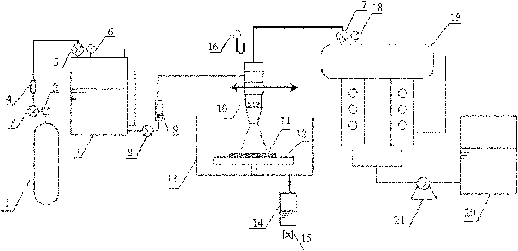
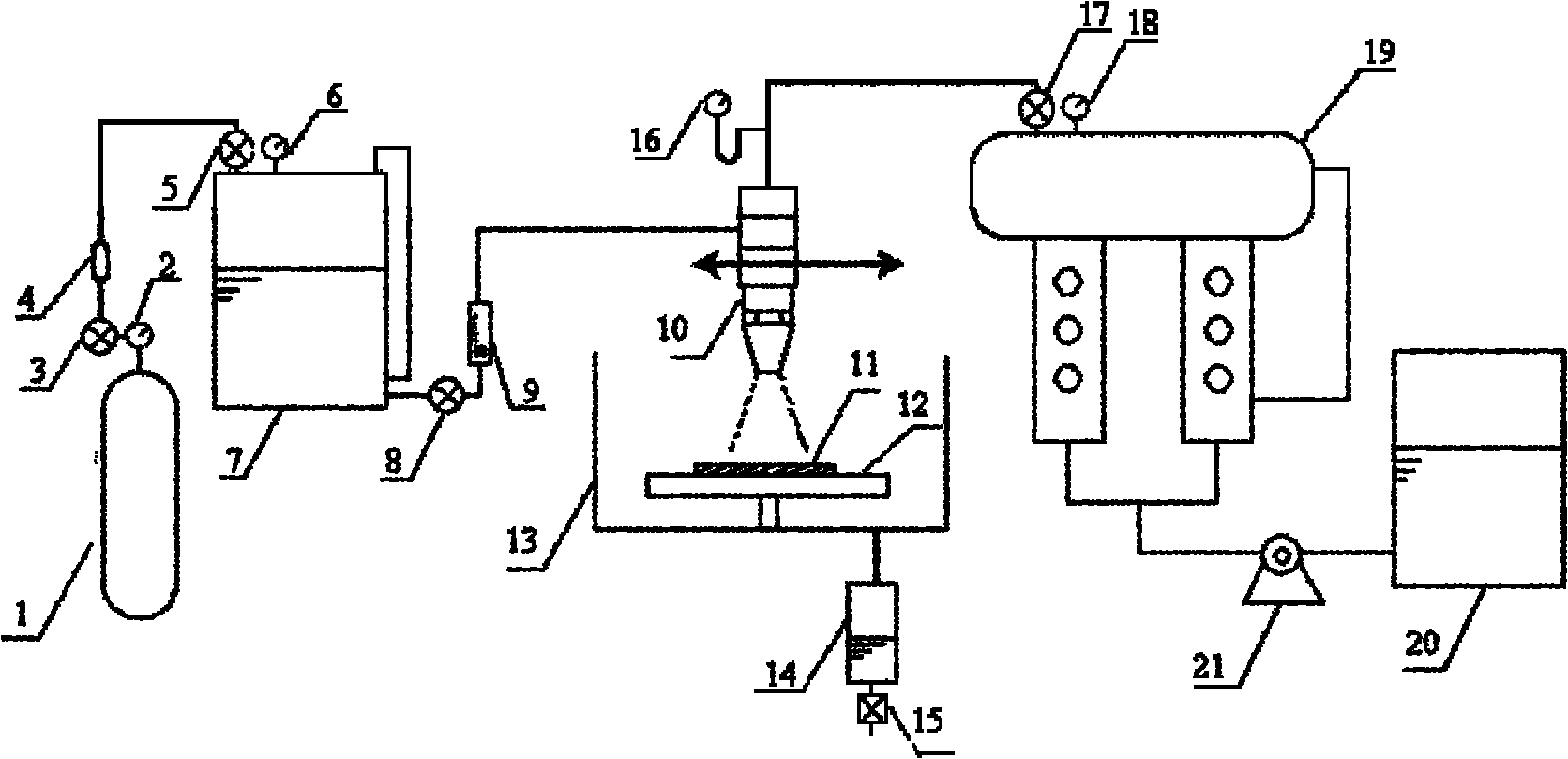
[0025] The process of the method is as follows: put the sample piece 11 into the tray 12 and fix it, the tray 12 can choose whether to rotate according to the needs; heat the heat exchanger 19 by setting the temperature value of the temperature control and display device 18, when the temperature reaches the required temperature (for example 300 ℃), adjust the pressure reducing valve 3, run the booster pump 21, adjust the flow meter 9; at this time N 2 The deionized water will pass through the valve 5, and the flow rate is controlled by the flow meter 9, and the deionized water will flow into the mixing chamber in the injection device 10. The deionized water will absorb heat through the heat exchanger 19 to form high-temperature steam at 100 ° C, and then pass through the valves in turn. 17. The pressure gauge 16 flows into the mixing chamber in the injection device 10; deionized water and high-temperature steam are mixed in the mixing chamber to form a mixed fluid with a ratio ...

Embodiment 2

[0027] The process of the method is as follows: put the sample piece 11 into the tray 12 and fix it, the tray 12 can choose whether to rotate according to the needs; heat the heat exchanger 19 by setting the temperature value of the temperature control and display device 18, when the temperature reaches the required temperature , adjust the pressure reducing valve 3, run the booster pump 21, adjust the flow meter 9; at this time N 2 The deionized water will pass through the valve 5, and the flow rate is controlled by the flow meter 9, and the deionized water will flow into the mixing chamber in the injection device 10. The deionized water will pass through the heat exchanger 19 to absorb heat to form high-temperature steam at 300 ° C, and then pass through the valves in turn. 17. The pressure gauge 16 flows into the mixing chamber in the injection device 10; deionized water and high-temperature water vapor are mixed in the mixing chamber to form a mixed fluid with a ratio of 60...

Embodiment 3

[0029] The process of the method is as follows: put the sample piece 11 into the tray 12 and fix it, the tray 12 can choose whether to rotate according to the needs; heat the heat exchanger 19 by setting the temperature value of the temperature control and display device 18, when the temperature reaches the required temperature , adjust the pressure reducing valve 3, run the booster pump 21, adjust the flow meter 9; at this time N 2 The deionized water will pass through the valve 5, and the flow rate is controlled by the flow meter 9, and the deionized water will flow into the mixing chamber in the injection device 10. The deionized water will pass through the heat exchanger 19 to absorb heat to form high-temperature steam at 500 ° C, and then pass through the valves in turn. 17. The pressure gauge 16 flows into the mixing chamber in the injection device 10; deionized water and high-temperature steam are mixed in the mixing chamber to form a mixed fluid with a ratio of 80%, and...


PUM


Abstract

The invention discloses a cleaning system. The cleaning system which comprises two deionized water storage tanks, a control device for heating deionized water to be in a high temperature state, a cleaning cavity and a jet device for jetting a mixed fluid containing deionized water and high temperature vapor to the cleaning cavity is characterized in that: the outlet of one deionized water storage tank is connected with one inlet of the jet device through the control device, and the outlet of the other deionized water storage tank is connected with one inlet of the jet device; and the outlet of the jet device is connected with the inlet of the cleaning cavity. The invention also discloses a cleaning method. The cleaning method comprises the following steps: 1, forming the high temperature vapor; 2, forming the mixed fluid containing deionized water and the high temperature vapor; and 3, cleaning a sample wafer with the mixed fluid. According to the cleaning system and the cleaning method in the invention, all of an inorganic carbonization thick layer, a bottom organic photoresist and SU-8 cure-crosslinked by the bottom organic photoresist can be peeled, so the photoresist removal efficiency is substantially improved, there are no residues, and the loss of a substrate material is minimized.

Description

technical field [0001] The invention relates to the technical field of semiconductors, in particular to a high-temperature steam and water mixed jet cleaning system and method. Background technique [0002] In modern CMOS devices, almost all substrate structures are formed via ion implantation. The energetic ions can damage the photoresist, making it difficult to remove. After implantation, these ions may exist as oxide layers, sub-oxide layers, or organic compounds. These energetic ions also transform the photoresist surface into a carbonaceous layer of diamond-type and graphite-type mixtures. The carbonization process therefore makes removal of implanted photoresist challenging. For the removal of implanted photoresist on silicon, alkaline or acidic fluorine-based solutions can be used, but it will cause loss of the underlying silicon; plasma removal technology can also be used, but the charge generated by the non-uniform plasma will damage the crystal. Sensitive struc...

Claims


Application Information

Patent Timeline
Patent Type & Authority Applications(China)
IPC IPC(8): G03F7/42B08B3/02
Inventor 王磊景玉鹏
Owner INST OF MICROELECTRONICS CHINESE ACAD OF SCI
Why Eureka
Try Eureka