

Ultraviolet light-emitting diode
A technology of light-emitting diodes and ultraviolet rays, which is applied to electrical components, circuits, semiconductor devices, etc., can solve problems such as low light extraction efficiency, transparency attenuation, and long optical path, so as to avoid aging problems, prolong service life, and improve light extraction efficiency. Effect
- Summary
- Abstract
- Description
- Claims
- Application Information
AI Technical Summary
Problems solved by technology
Method used
Image

Examples
Embodiment 1
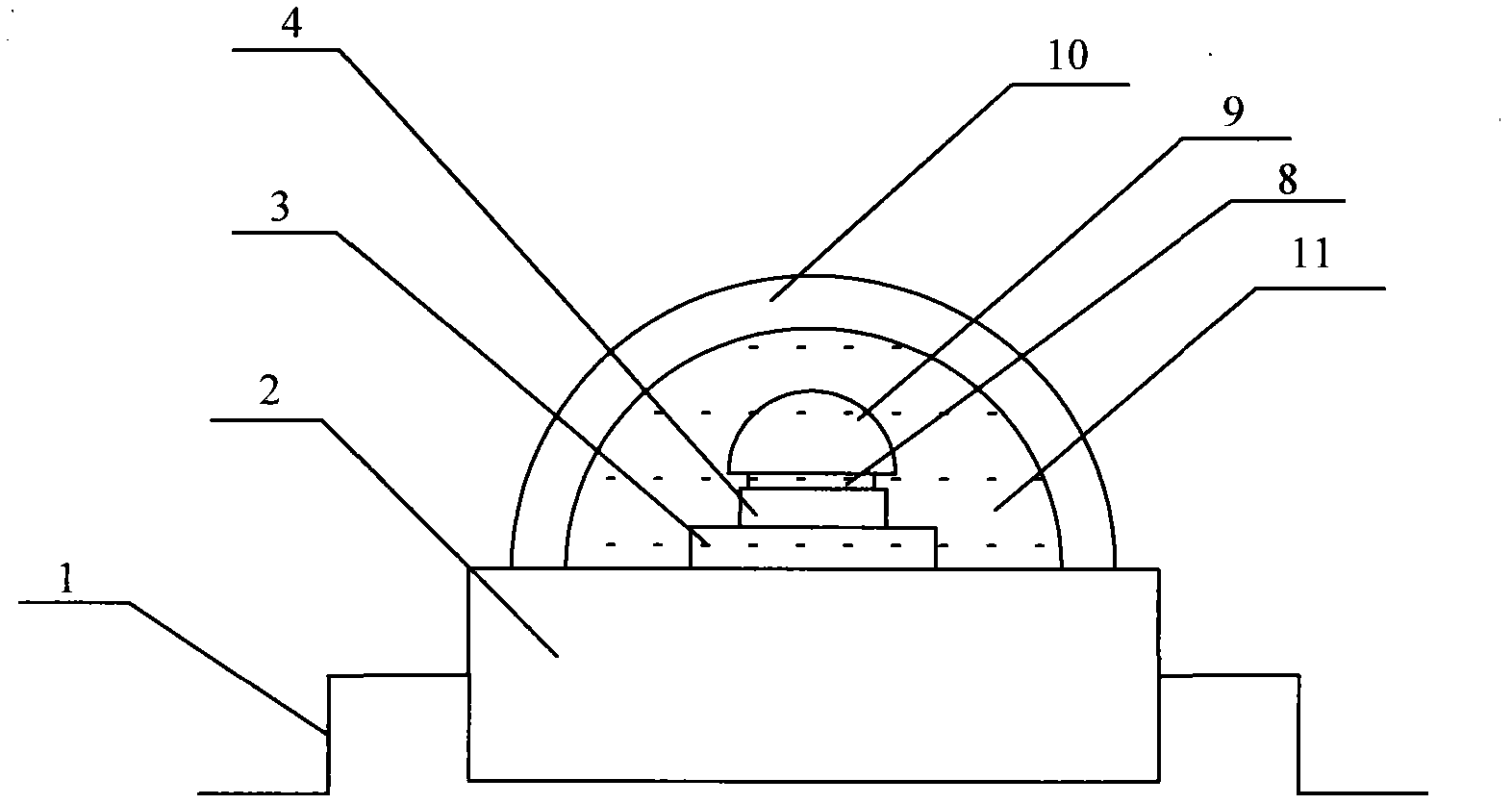
[0027] Embodiment 1. In order to improve the light-emitting efficiency of ultraviolet light, the ultraviolet light-emitting diode of this embodiment changes the existing state of the bare core of the light-emitting chip 4 when packaging the light-emitting chip 4 capable of emitting ultraviolet light. A spacer layer 8 is adhered to the light-emitting surface of the image 3 As shown, the spacer layer 8 requires a refractive index greater than 1.3 in the ultraviolet band and a transmittance greater than 50% in the ultraviolet band, so as to achieve the design purpose of improving the light extraction efficiency of ultraviolet light. In addition, a lens 9 needs to be further adhered on the spacer layer 8, and the lens 9 should also have a transmittance greater than 50% in the ultraviolet band. The lens 9, the spacer layer 8 and the light-emitting chip 4 are in a stacked relationship, and the adjacent two are tightly bonded, and the spacer layer 8 can be designed as thin as possib...
Embodiment 2
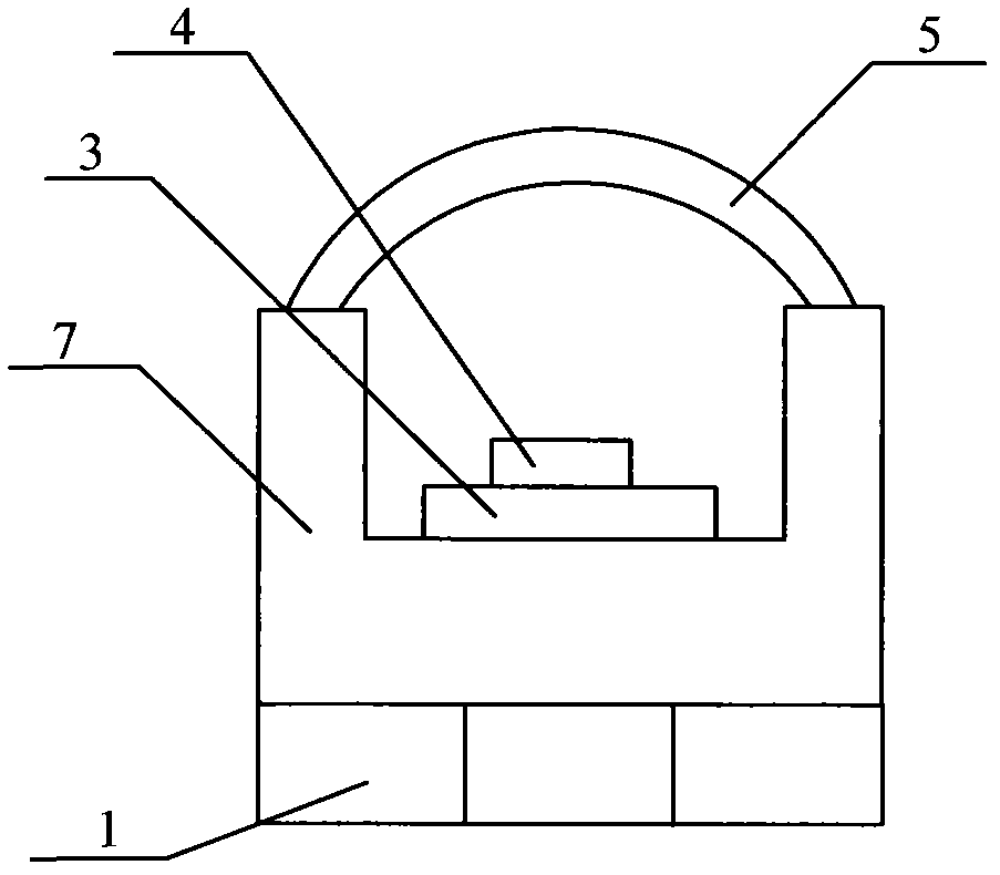
[0036] Embodiment two, see Figure 4 as shown, Figure 4 Another encapsulation method of ultraviolet LED is listed, in which the spacer layer 8 is still adhered to the light emitting surface of the light-emitting chip 4 that emits ultraviolet light according to the encapsulation method described in the first embodiment, and the lens 9 is adhered on the spacer layer 8 . The specific shape, material, size and other requirements of the spacer layer 8 and the lens 9 are the same as those described in the first embodiment, and this embodiment will not be described one by one here. In this embodiment, the lens 9 in the shape of a hemisphere is still used as an example for illustration. Of course, the lens 9 can also be designed into other non-planar shapes to reduce the total reflection phenomenon with the air interface, such as Figure 5 The top surface shown is in the shape of a rough, flat plate.
[0037] Connect the substrate of the light-emitting chip 4 to the cavity of the t...
Embodiment 3
[0042] Embodiment three, see Image 6 As shown, the packaging method of the ultraviolet LED in this embodiment is similar to that of the second embodiment, and also includes the lens 9, the spacer layer 8 and the light-emitting chip 4. The installation relationship between each part is the same as that of the first and second embodiments, and will not be repeated here. Wherein, the light-emitting chip 4 is also installed in the cavity of the tube shell 15, and the shape of the tube shell 15 is the same as that of the second embodiment, that is, the inner peripheral wall 15-2 of the cavity of the tube shell 15 and the bottom surface 12-1 of the cavity are also An included angle of 130°-140° is formed, and a reflective bowl is arranged on the inner peripheral wall 15-2 of the concave cavity of the tube shell. It is preferable to form an included angle α of 45° between the surface of the reflective bowl and the vertical direction, so as to improve the light extraction efficiency ...
PUM
| Property | Measurement | Unit |
|---|---|---|
| Thickness | aaaaa | aaaaa |
| Angle | aaaaa | aaaaa |
| Transmittance | aaaaa | aaaaa |
Abstract
Description
Claims
Application Information