Interference microscope and measuring apparatus

An interference microscope and interference fringe technology, applied in microscopes, measuring devices, interferometers, etc., can solve the problems of complex structures and inability to miniaturize devices, and achieve the effects of simple structures and improved work efficiency.

Inactive Publication Date: 2012-05-23
KK TOPCON
View PDF13 Cites 28 Cited by
  • Summary
  • Abstract
  • Description
  • Claims
  • Application Information

AI Technical Summary

Problems solved by technology

[0010] In addition, in Japanese Patent Application Laid-Open No. 11-83457, in order to change the optical path length, it is necessary to install a voltage-controlled variable wavelength filter, which is the same as Japanese Patent Laid-Open No. 2006-300792, which needs to be constituted as a complicated structure, and the device cannot be overall miniaturization

Method used


Image

  • Interference microscope and measuring apparatus
  • Interference microscope and measuring apparatus
  • Interference microscope and measuring apparatus

Examples


Embodiment Construction

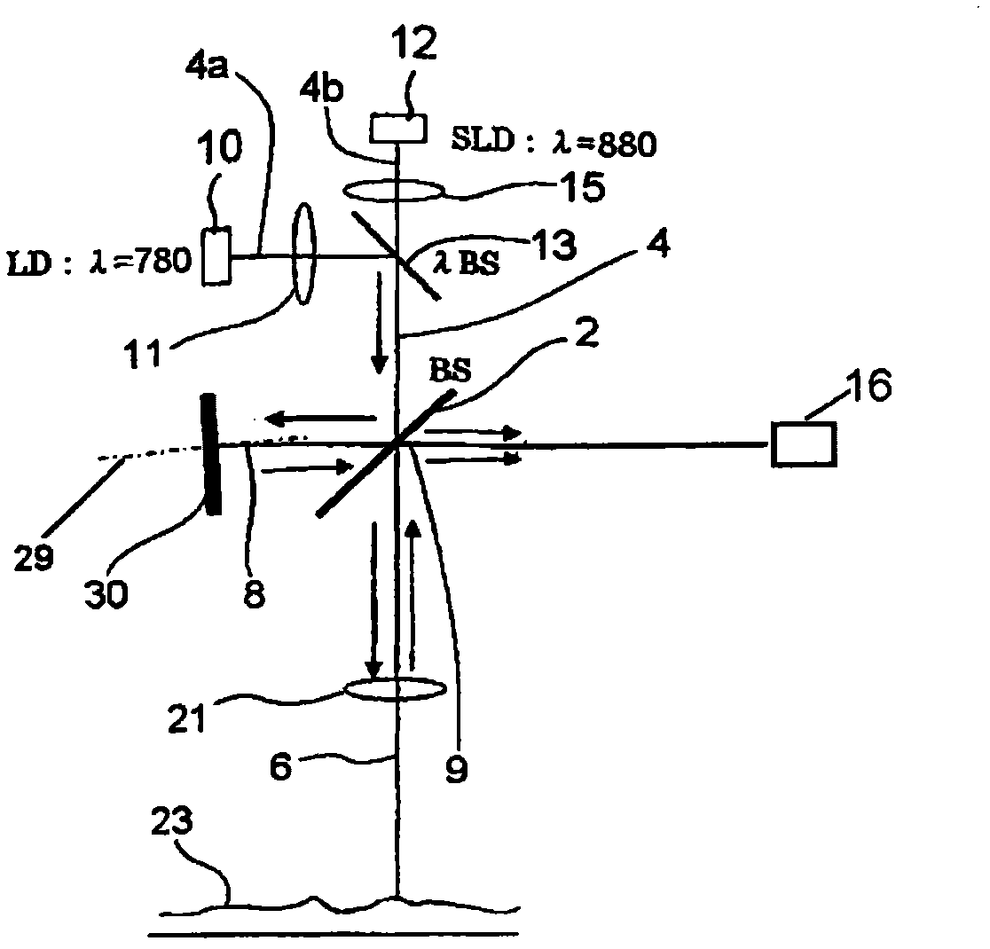
[0049] The interference microscope and measurement device of the present invention use various interferometers.

[0050] In a preferred embodiment of the invention, a Michelson interferometer is used. However, a Linick (phase shift type) interferometer may also be used as long as the effect of the present invention can be achieved.

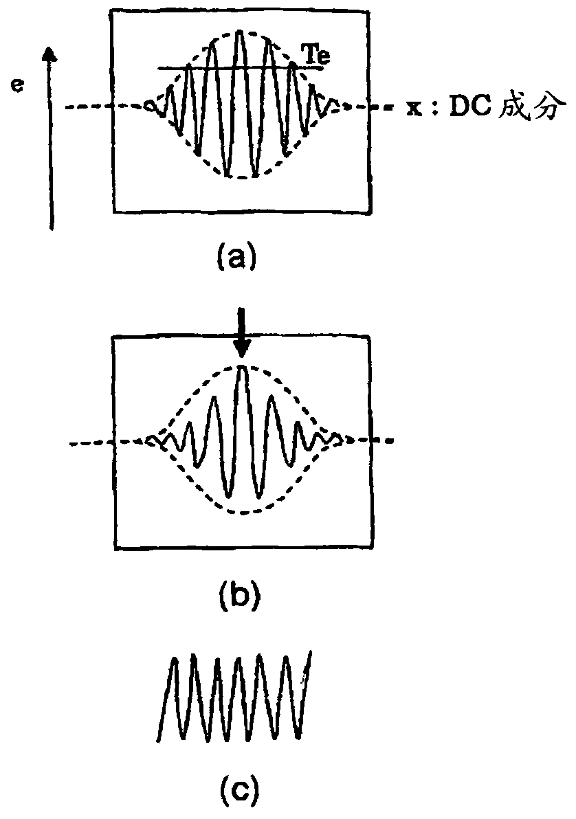
[0051] For reference, it is conceivable to use an interferometer of time domain refractometry as an interferometer, and to perform a micro-oscillation (micro-momentum Δλ) of the reference mirror (Ref) as shown below, for example.

[0052] λ=800nm

[0053] Δλ=30nm

[0054] Resolution: ΔZ=21m / π·λ 2 / Δλ

[0055] =9.4μ

[0056] Horizontal resolution: ΔX=4λ / π f / d

[0057] The scanning area in the direction of the optical axis is 2Z o =ΔX 2 π / 2λ.

[0058] However, in this case, the resolution is limited, and it is not easy to inspect the shape of ultrafine regions such as dust and pole pieces on the object to be measured (sample) suc...


PUM

PropertyMeasurementUnit
wavelengthaaaaaaaaaa

Abstract

Provided are an interference microscope wherein samples, such as a wafer, are irradiated with a laser beam, and the inside of the sample surface is observed and inspected by using an interferometer, and a measuring apparatus. A reference light path for guiding light to between a beam splitter and a reference mirror is arranged, and a measuring light path for guiding light to between the beam splitter and the sample is also arranged, thus, an optical light path difference is provided between the reference light path and the measuring light path. Furthermore, interference fringes are formed in a detecting means by slightly tilting the reference mirror. With such simple constitution, the surface shapes of the samples (subjects to be measured), such as the wafer, are measured only by slightly tilting the reference mirror, and accurate coordinate positions of dusts, pole piece and the like can be specified.

Description

technical field [0001] The present invention relates to an interference microscope and a measurement device for observing and inspecting surface or internal unevenness of a sample (measurement object) such as a wafer using an interferometer such as a Michelson interferometer or a Linick interferometer. Background technique [0002] Hitherto, a measurement device using an interferometer that divides incident light into two optical paths, one of which irradiates the sample (object to be measured), and the other of which irradiates a reference mirror, makes the light from the sample The reflected reflected light interferes with the reference light to form interference fringes, thereby observing and inspecting the inside of the surface of the sample. [0003] In Japanese Patent Application Laid-Open No. 2006-116028, when forming interference fringes, the reference mirror can be moved in the direction of the optical axis by the piezoelectric element PZT, so that the phase shift u...

Claims


Application Information

Patent Timeline
Patent Type & Authority Applications(China)
IPC IPC(8): G01B9/02G01B11/24G01N21/956
CPCG01B11/2441G01B9/02032G01B9/0209G01B9/02007G02B21/0016G01B2290/45G01N21/9501G01B9/02G01B9/04
Inventor 大友文夫布川和夫籾内正幸矶崎久宫川一宏
Owner KK TOPCON
Why Eureka
Try Eureka