Three-dimensional image capture device

A technology of three-dimensional imaging and solid-state imaging elements, which is applied in the field of three-dimensional imaging technology, can solve problems such as image sensitivity reduction, and achieve the effect of high precision

Inactive Publication Date: 2012-05-23
PANASONIC CORP
View PDF3 Cites 9 Cited by
  • Summary
  • Abstract
  • Description
  • Claims
  • Application Information

AI Technical Summary

Problems solved by technology

In the process of capturing an image with parallax, the situation is basically the same as that shown in Patent Document 2, and the sensitivity of the image is greatly reduced

Method used


Image

  • Three-dimensional image capture device
  • Three-dimensional image capture device
  • Three-dimensional image capture device

Examples


Embodiment approach 1

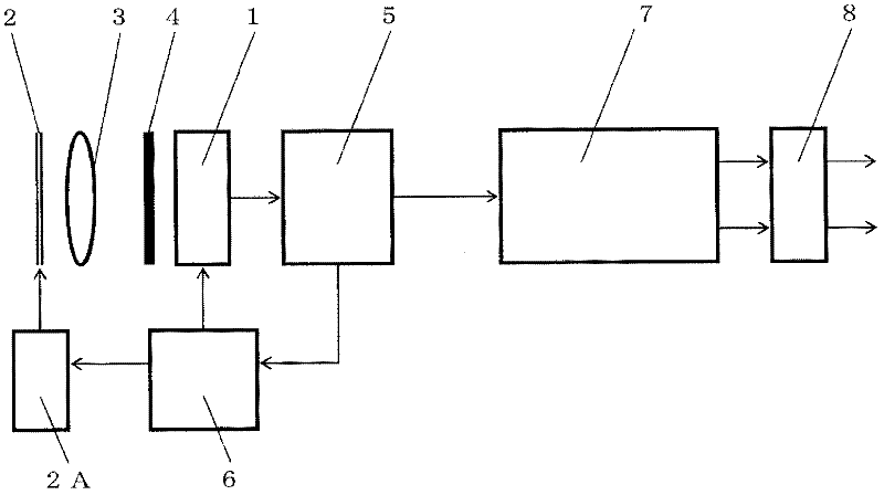
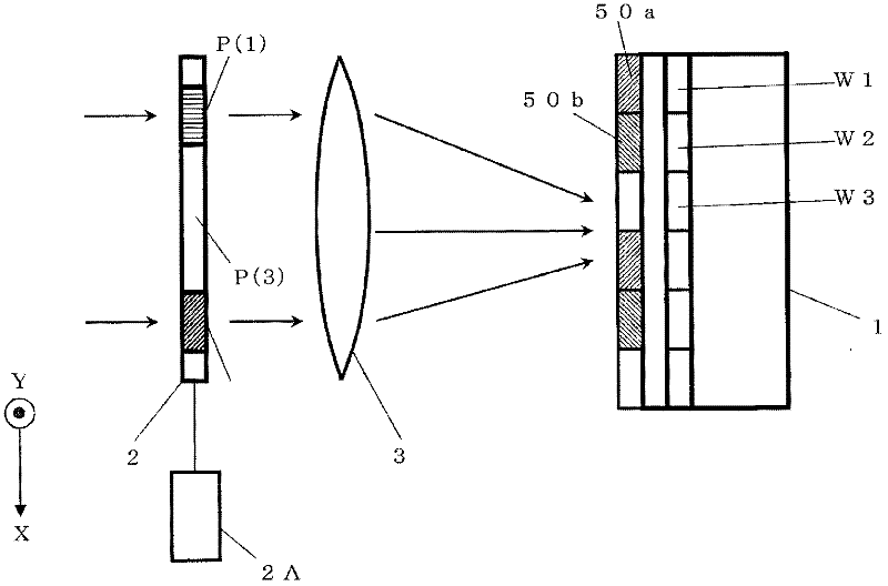
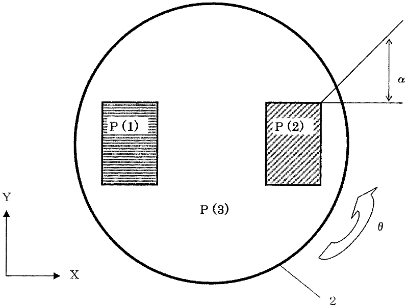
[0055] figure 1 It is a configuration diagram of the imaging device in the first embodiment of the present invention. 1 is a solid-state imaging device that performs photoelectric conversion, 2 is a light-transmitting plate having a part of a polarization region, 2A is a rotation drive unit that rotates the light-transmitting plate 2 in the direction of the optical axis as the rotation axis, and 3 is for controlling A circular optical lens for forming an image by incident light, 4 is an infrared cut filter, 5 is a signal generation and image signal receiving unit that generates an original signal for driving a solid-state imaging element and receives a signal from the solid-state imaging element, and 6 7 is an element drive unit that generates a signal for driving a solid-state imaging element, and 7 is an image signal that processes an image signal to generate a multi-viewpoint image, an image (difference image) representing a difference between the multi-viewpoint images, a...

Embodiment approach 2

[0139] Below, refer to Figure 8 , 9 A second embodiment of the present invention will be described. The imaging device of this embodiment differs from the imaging device of Embodiment 1 in the basic pixel configuration of the imaging element 1 and the method of acquiring an image representing parallax. Hereinafter, only the differences from the imaging device of Embodiment 1 will be described, and the description of the same parts will be omitted.

[0140] Figure 8 The basic pixel configuration on the imaging surface of the solid-state imaging device 1 in this embodiment is shown. In this embodiment, a pixel is constituted by a plurality of pixel blocks basically constituted by two rows and two columns, and a color element (color filter) or a polarizing filter is arranged to face each pixel. The color element in this embodiment is a known color filter that transmits only light in a wavelength range having a specific color component. In addition, in the following descrip...


PUM


Abstract

Disclosed is an image capture device, comprising an image forming lens (3), a light transmission unit (2) further comprising two polarizers, a rotation drive unit (2A) that rotates the light transmission unit (2), and a solid-state image capture element (1). The solid-state image capture element (1) further comprises a plurality of pixels and polarizing filters corresponding to the pixels. A first polarizing filter (50a) is positioned corresponding to a first pixel group (W1), and a second polarizing filter (50b) is positioned corresponding to a second pixel group (W2). The directions of the transmission axes of polarization regions (P(1), P(2)) in the light transmission unit (2) vary respectively by an angle a. The directions of the transmission axes of the polarization filters (50a, 50b) vary respectively by an angle ss. The rotation drive unit (2A) is capable of rotating the light transmission plate (2) with the direction of the optical axis of the incident light being the direction the axis of rotation. It is thus possible to obtain a plurality of sets of multiple-viewpoint images.

Description

technical field [0001] The present invention relates to a single-lens three-dimensional imaging technology that uses an optical system and an imaging element to obtain multiple images with parallax. Background technique [0002] In recent years, digital still cameras and digital video cameras employing imaging elements such as CCDs and CMOSs ​​have surprisingly achieved higher functionality and higher performance. Especially with the advancement of semiconductor manufacturing technology, a high degree of refinement has been developed, and high integration has been realized. The imaging element has also advanced from 1 million pixels to 10 million pixels to achieve high pixel count, and the captured images have also achieved high-quality images by leaps and bounds. In addition, the display device also achieves space saving due to the thin liquid crystal or plasma display, and realizes high-resolution, high-contrast performance. Such high-quality images are trending, and tar...

Claims


Application Information

Patent Timeline
Patent Type & Authority Applications(China)
IPC IPC(8): G03B35/04H04N5/225H04N13/02
CPCH04N13/0203G03B35/08H04N13/021H04N13/0217H04N13/211H04N13/218H04N13/204
Inventor 平本政夫三崎正之泷泽辉之铃木正明
Owner PANASONIC CORP
Why Eureka
Try Eureka