
Curve charging and braking system for electric automobile

A technology for electric vehicles and braking systems, which is applied in the direction of electric braking systems, electric vehicles, and track installations, can solve the problems of no technical solutions and waste of energy for electric vehicles, and achieves simple structure, easy promotion and use, and increased The effect of adhesion

Inactive Publication Date: 2012-05-30
XIAN SHENKE ELECTRONICS RES INST
View PDF0 Cites 0 Cited by
  • Summary
  • Abstract
  • Description
  • Claims
  • Application Information

AI Technical Summary

Problems solved by technology

However, as far as the working principle and vehicle structure of pure electric vehicles are concerned, they are still in the exploratory stage and there is no very mature technical solution. So far, no enterprises and research institutions have been able to better solve the technical problems of electric vehicles. , and the energy management of electric vehicles is the key to the technical problems of electric vehicles. Considering that electric vehicles have a relatively large centrifugal force when turning, the faster the speed, the greater the centrifugal force. For safety, ordinary drivers must take brakes. Braking will seriously waste the energy of electric vehicles. At present, there is no solution that is not only safe and reliable, but also helpful for the energy management of electric vehicles to improve this situation.

Method used


Image

  • Curve charging and braking system for electric automobile
  • Curve charging and braking system for electric automobile
  • Curve charging and braking system for electric automobile

Examples


Embodiment Construction

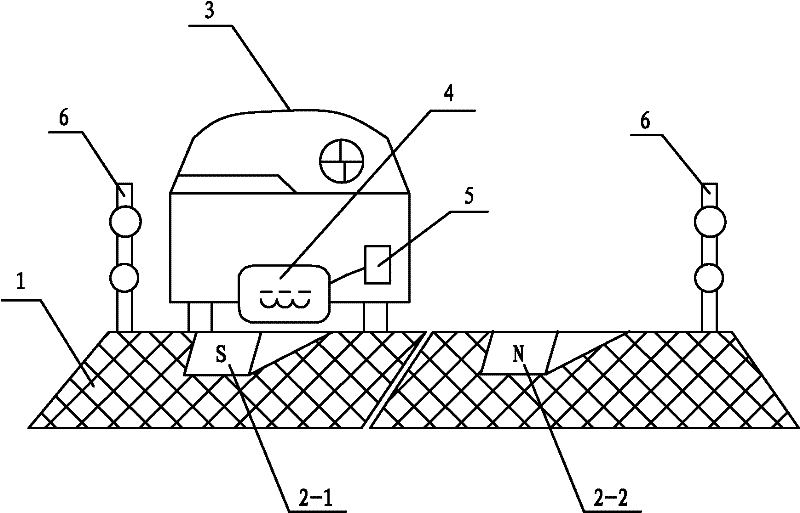
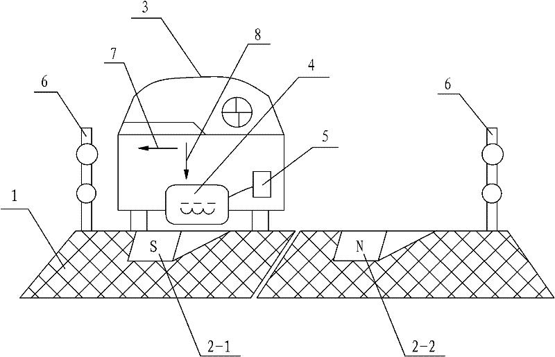
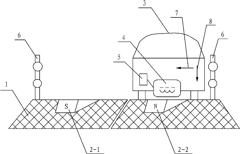
[0023] Such as figure 1 As shown, the present invention comprises the magnet that is arranged under the road surface of curve 1 and the charging energy receiver 4 that is arranged at the bottom of electric vehicle 3, and described magnet comprises the magnet 2-1 that is arranged on the inner side of curve and the magnet 2-1 that is arranged under the road surface inside curve 1 The curve outside magnet 2-2 arranged under the road surface on the outside of curve 1, the polarity of the curve inside magnet 2-1 and the curve outside magnet 2-2 are set in opposite directions and both bend along curve 1 The direction is offset at a certain angle, and one pole of the inner magnet 2-1 of the curve and the outer magnet 2-2 of the curve point to the center of the circle of the curve 1 along the direction in which the electric vehicle 3 is coming, and the charging energy receiver 4 is connected with the accumulator 5 on the electric vehicle 3 and controls the charging of the accumulator ...


PUM


Abstract

The invention discloses a curve charging and braking system for an electric automobile. The curve charging and braking system comprises a magnet arranged below a curve road surface and a charging energy receiver arranged at the bottom end of the electric automobile, wherein the magnet comprises a curve inner side magnet arranged below a curve inner side road surface and a curve outer side magnet arranged below a curve outer side road surface; the curve inner side magnet and the curve outer side magnet are arranged in an opposite polarity way, and are arranged by being deviated from a curve turning direction by a certain angle; the poles of the curve inner side magnet and the curve outer side magnet along the coming direction of the electric automobile point to a curve turning circle center; and the charging energy receiver is connected with a storage battery on the electric automobile, and is used for controlling the storage battery to charge. The curve charging and braking system has the advantages of simple structure, novel and reasonable design, saving in effective power, environmental friendliness, energy saving, high practicability, increase in the safety performance of the electric automobile, contribution to energy management of the electric automobile, good use effect, and convenience in popularizing and applying.

Description

technical field [0001] The invention belongs to the technical field of electric vehicles, in particular to a curve charging and braking system for electric vehicles. Background technique [0002] So far, gasoline, diesel and other fuel vehicles account for the vast majority of vehicles. These vehicles have mature design and manufacturing technology and good performance, which can meet people's needs for travel. However, these cars will produce a large amount of exhaust gas during driving, especially CO, HC, NOX, particles, odor and other pollutants in the exhaust gas to form acid rain, acid fog and photochemical smog. These harmful substances have become the largest source of environmental pollution. It poses a serious threat to human health and people's lives. Due to the massive consumption of non-renewable resources represented by oil, the energy problem is becoming more and more serious. Therefore, electric vehicles with zero emissions and no pollution and various new ty...

Claims


Application Information

Patent Timeline
Patent Type & Authority Applications(China)
IPC IPC(8): B60L5/00B60M7/00B60L7/00
Inventor 苏西安盛熙
Owner XIAN SHENKE ELECTRONICS RES INST
Learn More