Manufacture method of permanent magnet
A manufacturing method and technology of permanent magnets, which are applied in the manufacture of permanent magnets, inductors/transformers/magnets, electrical components, etc., can solve problems such as low energy consumption, and achieve the effects of low equipment cost, high degree of orientation, and uniform magnetic properties.
- Summary
- Abstract
- Description
- Claims
- Application Information
AI Technical Summary
Problems solved by technology
Method used
Image

Examples
Embodiment 1
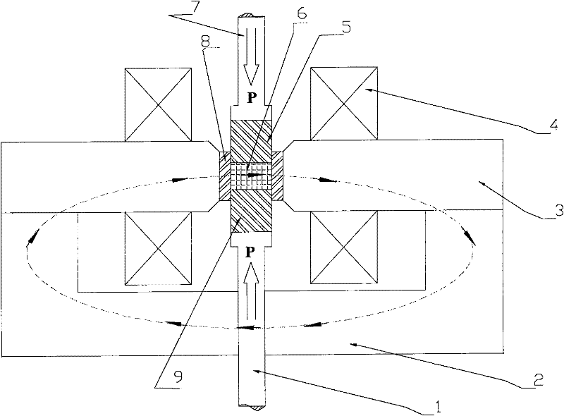
[0035] attached image 3 According to the first embodiment of the present invention, the alternating magnetic field with a constant amplitude and a frequency of 0.1 to 100 Hz is used to orient the permanent magnet alloy powder, and the device for producing a permanent magnet with a high degree of orientation with a low orientation magnetic field intensity is a front sectional view ( image 3 (a)) and top sectional view ( image 3 (b)). The magnetic field generated by the coil 11 forms a magnetic circuit through the magnetically permeable yoke 10, and the path and direction of the magnetic field lines in the magnetic circuit at a certain moment are as follows: image 3 As shown by the dotted line superimposed with arrows in the top sectional view of (b), a working magnetic field air gap is formed at the symmetrical center of the yoke 10, and the female mold 14 is placed in the magnetic field air gap. After the lower pressing rod 15 drives the lower punch 16 to move upward int...
Embodiment 2
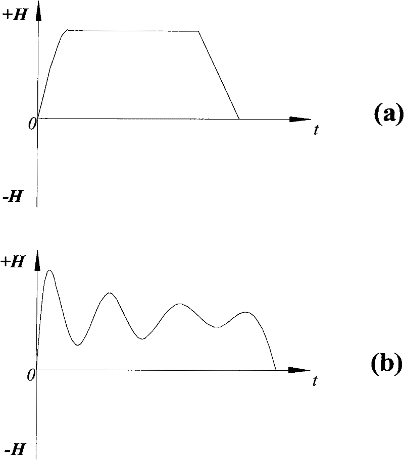
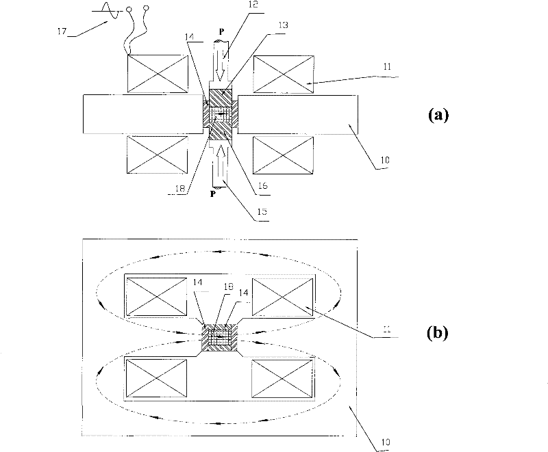
[0041] Figure 5 According to the second embodiment of the present invention, it is shown that the alternating magnetic field with a constant amplitude and a frequency of 0.1 to 100 Hz is used to orient the permanent magnet alloy powder, and the device for producing a permanent magnet with a high degree of orientation with a low orientation magnetic field intensity is a front sectional view ( Figure 5 (a)) and top sectional view ( Figure 5 (b)). Compared with the first embodiment, the coil 11 forming the alternating magnetic field in this embodiment is a single air-core coil, the female mold 14 is located at the central symmetrical position in the coil 11, and the Nd-Fe-B alloy magnetic powder is placed in the female mold 14 ; Input 380V, 50Hz electric current by AC power supply 17 in coil 11, form such as in alloy powder district 18 Figure 4 An alternating magnetic field with both forward and reverse magnetic fields is shown with a constant amplitude. The amplitude of t...
Embodiment 3
[0046] Image 6 According to the third embodiment of the present invention, the alternating magnetic field with a constant amplitude and a frequency of 0.1 to 100 Hz is used to orient the permanent magnet alloy powder, and the device for producing a permanent magnet with a high degree of orientation with a low orientation magnetic field intensity is a front sectional view ( Image 6 (a)) and top sectional view ( Image 6 (b)). Compared with the second embodiment, the coil 11 of this embodiment is a single square coil, and the periphery of the coil 11 is equipped with a magnetically permeable yoke 19 stacked with silicon steel sheets, and the female mold 14 is in the center of the coil 11 Symmetrical position, Nd-Fe-B alloy magnetic powder is placed in the female mold 14; 380V, 50Hz current is input into the coil 11 through the AC power supply 17, and the alloy powder area 18 is formed as Figure 4 An alternating magnetic field with both forward and reverse magnetic fields is...
PUM
 Abstract
Description
Claims
Application Information
 - R&D
- Intellectual Property
- Life Sciences
- Materials
- Tech Scout
- Unparalleled Data Quality
- Higher Quality Content
- 60% Fewer Hallucinations
Browse by: Latest US Patents, China's latest patents, Technical Efficacy Thesaurus, Application Domain, Technology Topic, Popular Technical Reports.
© 2025 PatSnap. All rights reserved.Legal|Privacy policy|Modern Slavery Act Transparency Statement|Sitemap|About US| Contact US: help@patsnap.com